Hi enthusiasts in this post we will see How do Phase Shift Oscillators Work.
Oscillators that can produce a stable sinusoidal signal at the output are termed Phase Shift Oscillators.
Normally, the Phase Shift Oscillators circuit consists of a transistor-like amplifier unit or op-amp accompanied by a feedback network that comprises capacitors and resistors, which is also termed an RC phase shift oscillator.
Don’t miss to read How Flip-Flops Work
RC Phase Shift Oscillator
RC usually refers to the amalgam of resistor and capacitor which produces the oscillator out phase shift.
The feedback path which usually has the RC network is attached in a ladder fashion which is often called an RC phase shift oscillator.
The output voltage leads the input for a sinusoidal waveform for an RC circuit.

RC oscillators consist of inverting amplifiers (invertors and transitional amplifiers), resistors, and capacitors. The pros of the inverting amplifiers are they provide infinite gain and finite input impedance.
The amplifiers generate 180 degrees phase shift and the phase shift network also generates a phase shift of 180. The RC oscillator uses the phase shift generated by these both components.
The Input of the RC oscillator usually generated by the phase angle is dependent on the values of the RC components.
The RC oscillators are known to have sustained oscillations. The oscillator loop gain must be equal to 1.
The circuit phase shift should be equivalent to 0 or 360⁰, The phase shift generated by the amplifier circuit is usually 180⁰.
For the RC phase shift oscillator to attain sustained oscillations, the phase shift gained by the feedback path should also be 180⁰.
So the complete phase shift achieved will be 0 or 360⁰. The loop gain which is usually equal to 1 can be attained by tuning the gain of the amplifier and the feedback circuit.
RC Feedback Network
The RC phase shift network consistent with a capacitor and a resistor, is illustrated in the image below.

As discussed earlier, the output usually is the precedence of the input, the circuit is also termed a Phase lead circuit.
From the above circuit, the transfer function of the circuit is

So, the phase shift is

By observing the equation from above, it is clear that the values of R and C impact the phase shift.
φ will be equal to 0⁰ for a small value of XC. If R is very small or 0 then it will cause XC/R to get equal to infinity, thus in this case φ will be 90⁰.
So from the discussions above, it can be stated that a phase shift between 0 to 90⁰ is being produced by the feedback circuit.
But, in order to achieve the phase shift of 180⁰ for the phase shift oscillator, the value of R in the circuit should be as low as possible, 0 to be precise.
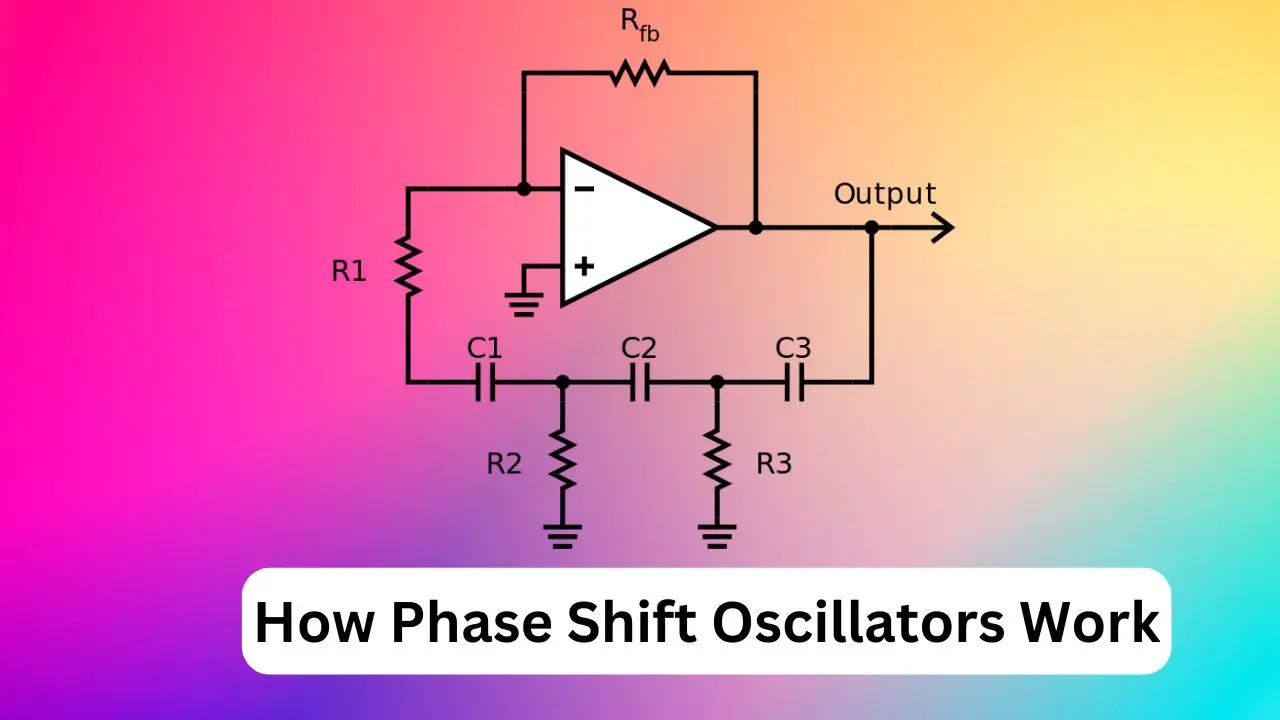
Phase Shift Oscillator Using Op-Amp
The phase shift oscillator using an operational amplifier shown below

The amplifier consists of three capacitors and 4 resistors. Let us presume the value of resistors R1 = R2 = R3 = R and capacitors C1 = C2 = C3 = C.
The oscillation frequency is as follows
f=1/(2πRC√2N) where N is the total number of stages. If the number of stages is 3 then the equation is as follows
f =1/(2лRC √б) The oscillation criterion is Rfb = 29. R.
Where Rfb is the feedback resistor
The above condition is by bearing in mind all resistors equal to R except the resistor in negative feedback.
If not, the calculations become very complex. The frequency of oscillations shown as:
Fo = 1/2π (R2R3 (C1C2 + C1C3 + C2C3) + R1R3 (C1C2 + C1C3) + R1R2C1C2)1/2
In order to balance the ladder, network of capacitors and resistors connected in the feedback, a high gain is required to be generated by the single op-amps circuit.
It helps to sustain the oscillations. A gain of 10 will be enough for the oscillator if the RC network is solid.
A buffer can be placed in each RC network in the circuit, which reduces load by making sure the oscillations are done without any disturbance.
Pros of Phase Shift Oscillators
- Eliminates the need for transformers or inductors.
- The frequency range of the amplifiers is high and has very good stability.
- Works fine with low frequencies.
- The design is simple with a few parameters.
- Sine waves will be output causing little distortion
- When compared with other electronic oscillators these are fairly economical.
Cons of Phase Shift Oscillators
- As the feedback produced is limit to terms, it will be tough for the circuit to produce oscillations.
- The output generated has less feedback.
Glad all your questions on how do Phase Shift Oscillators Work said here, Thank you for reading.
As an Amazon Associate, I earn commission from qualifying purchases.


