Smart Glasses for the Blind without Arduino

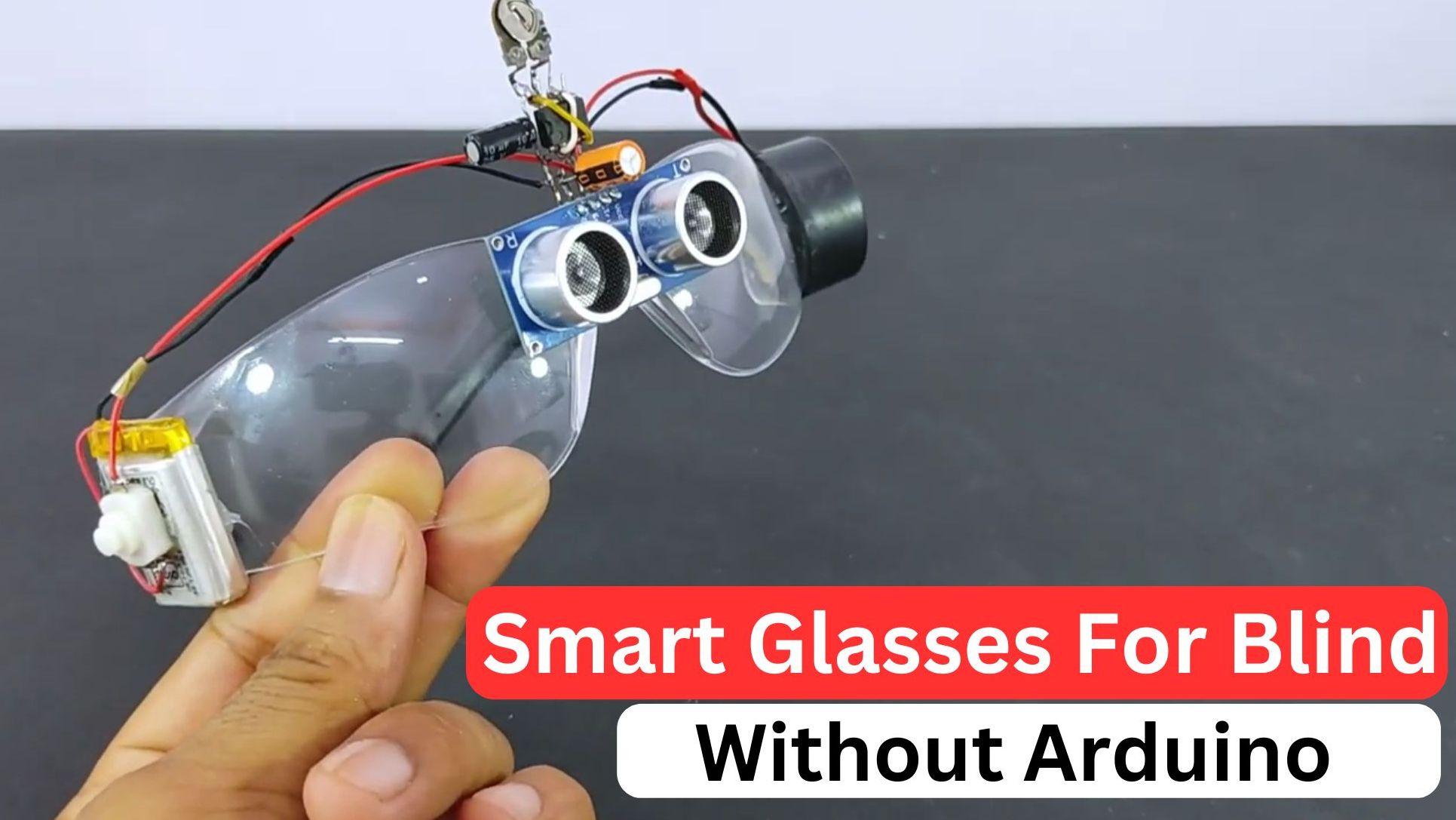
In this project, we will see how to make smart glasses for the blind without Arduino with complete instructions.
This is a useful DIY project if you are thinking of making something useful.
A few days back I was walking on the streets and saw a blind man struggling to walk on the busy street.
They had a stick in their hand and they had to always tap on the ground to check for any obstacle nearby
This worked well for them for the lower half part, but for the head part, there was nothing.
So I wanted to make a device that would be wearable and useful for them, this was an inspiration for me.
Another interesting project of Automatic solar tracking which you might like
Why I’m not using Arduino for the blind glass project
I researched a few things online and saw many variants of Arduino-based smart glass for the blind.
Since using Arduino made the project bigger and more costly I went on searching for some alternatives.
In the end, I have come up with some easy and budget-friendly materials for this project.
Why go for an expensive one when you can make it on a budget, Yes i know Arduino has more capability but we don’t want those in this project.
This is very affordable and the total build cost is less than 10$ or 800inr.
To begin with we will make a list of supplies for this project.
Materials for smart glasses without Arduino
- 555 Timer IC
- Ultrasonic sensor
- 10k ohm preset potentiometer
- 10micro farad capacitor
- Goggles or glasses
- 1k ohm resistor
- Buzzer
- 3.7v battery
- Hot Glue
- Few pieces of wires for connections

Roles of IC timer 555 and other electrical components
To make it easier I will explain the role of each component.
555 Timer IC
The 555 Timer IC or integrated circuit is used for generating various types of timing and pulse waveforms.
In this smart glasses project, the 555 Timer IC creates timing generating (PWM) or pulse-width modulation signals for the buzzer.
Ultrasonic Sensor
The ultrasonic sensor emits ultrasonic waves and measures the time it takes for those waves to bounce back after hitting an object.
This is the main sensing component in our Ultrasonic smart glasses.
This data is used to calculate the distance between the glasses and nearby objects.
In our blind glasses, the ultrasonic sensor is the primary input device, providing information about obstacles in the wearer’s path.
10k ohm Preset Potentiometer
The potentiometer (variable resistor) allows you to adjust resistance manually. In our project, it is used for sensitivity adjustment of the ultrasonic sensor.
This adjustment is helpful in changing the distance range at which the glasses detect obstacles.
10 microfarad Capacitor
In this circuit, the capacitor filters or smoothes out electrical signals. For example, it helps to stabilize voltage levels and reduce noise in the power supply.

Roles of Other Components
The contributions of each component explained
Goggles or Glasses
These are the mounts for the electronic components. The glasses provide the wearable option.
1k ohm Resistor
A resistor restricts the flow of current in a circuit. In our smart glasses, the 1k ohm resistor is used in various parts of the circuit to control current flow and limit voltage levels for signal conditioning.
Buzzer
In our smart blind glasses, the buzzer is used to provide auditory feedback to the wearer about the presence of obstacles.
3.7V Battery
The battery is the power source for your smart glasses. It provides the necessary power to operate all the components.
Smart glasses for the blind without Arduino circuit diagram
This is the circuit we are using to build this project.
The circuit has the names of the components on it so as to make the connectivity easier without any problem.
You can have a look at the circuit and start to solder the components one by one.
This won’t take much longer if you have soldered before.

Note that use flexible kind of wires to solder the component as we are installing this on a glass later.
I started soldering the ultrasonic sensor terminals first followed by the IC timer circuit.
In the battery that I chose to use in this project, I already added a switch so that it becomes easy to on and off.
After you have the circuit ready we can install it on the glass and I like this step.

For a better understanding of the visual, I have given the names of the build steps.
On the first one you can see that the circuit is almost complete only thing pending was adding on glasses.
The second image shows the placement of components, I placed the ultrasonic sensor on the front later I placed the buzzer on the side.
You can also use a much smaller size buzzer even if they give out the same output.
On the other side of the ear place the battery pack with a switch and use hot glue to attach them to the glass frame.
This completes the building of the ultrasonic smart glasses for the blind.
How to use ultrasonic smart glasses for the blind
With the wearable device ready all you have to do before using is switch it on and wear it like ordinary glasses.
After you wear this device whenever an obstacle is detected by the ultrasonic sensor the buzzer makes a noise.
This is very helpful for the blind when they are walking on the streets
After using you can recharge the battery all you have to do is disconnect the battery recharge and reconnect
There are a lot of advanced features that I will be adding in the future, stay tuned and comment if you have any suggestions.

This was the complete tutorial on building smart glasses for the blind hope you will find it informative.
If you have any questions please ask us in the comments we will be glad to help.
The complete working project video of smart glasses for the blind without Arduino is available here thank you Pendech for ideas.
As an Amazon Associate, I earn commission from qualifying purchases.


