Hi readers in this tutorial we will see how Flip Flops work with all its details like truth table and Circuit Diagram.
A flip-flop is a circuit that has two stable states.
Binary data stored in these stable states by virtue of varying inputs applied to them.
Flip-flops and latches are primarily in use for data storage but, they differ in their working.
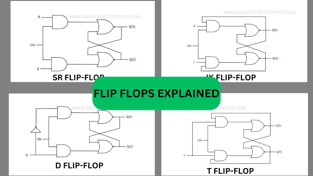
Flip Flop Types
The different kinds of Flip-flops used in digital electronics are
- SR Flip-flop
- JK Flip-flop
- D Flip-flop
- T Flip-flop
Now we will see one by one How Flip Flops Work of these given types.
SR Flip-Flop
SR Flip-flop also known as Set-Reset Flip-flop and most widely used in digital systems.
It only operates with positive and negative clock transitions. The circuit diagram of SR Flip-flop is below

SR Flip-flop has two inputs S and R with two outputs Q(t) and Q(t)’.
The Set input ‘S’ used to produce the value of 1 and the Reset input ‘R’ used to produce a value of 0.
The reset input enables the Flip-flop to get to it’s initial state from the present condition with a output of Q(t).
The truth table of SR Flip-flop is as follows
| S | R | Q(t) | Q(t) |
| 0 | 0 | 0 | 1 |
| 0 | 1 | 0 | 1 |
| 1 | 0 | 1 | 0 |
| 1 | 1 | ∞ | ∞ |
JK Flip-Flop
JK Flip-flop is the improvised version of SR Flip-flop.
Positive and negative transitions occur on the JK Flip-flop.
The below figure shows the circuit diagram of JK Flip-flop.

The circuit has the input J and K with the outputs Q(t) and Q(t)’. The SR Flip-flop and the JK Flip-flop operate in a similar way.
Here S =JQ(t)’ and R = KQ(t) can be termed as the inputs of the SR Flip-flop for the purpose of utilizing SR Flip-flop for 4 different inputs.
The state table of JK Flip-Flop shown in the table below
| J | K | Q t+1 |
| 0 | 0 | Q(t) |
| 0 | 1 | 0 |
| 1 | 0 | 1 |
| 1 | 1 | Q(t) |
Here, the present and next state represented by Q t and Q t+1 respectively.
When a positive transition of the clock signal are applied, the JK Flip-flop can be used for four different functions.
Hold, Reset, Set and Complement of the present conditions depending on the input conditions.
The below table shows the characteristics of the JK Flip-flop.
| Present Input | Present Input | Present State | Next State |
| J | K | Q(t) | Q(t+1) |
| 0 | 0 | 0 | 0 |
| 0 | 0 | 1 | 1 |
| 0 | 1 | 0 | 0 |
| 0 | 1 | 1 | 0 |
| 1 | 0 | 0 | 1 |
| 1 | 0 | 1 | 1 |
| 1 | 1 | 0 | 1 |
| 1 | 1 | 1 | 0 |
D Flip-Flop
The D Flip-flip commonly seen in the operation of the shift registers, counters, and the input synchronization systems.
The changes in the input values do not affect the output of the D Flip-flop unless the clock signal is of the active transition. The visual representation of D Flip-flip shown below

The D Flip-flip has a single input D and has two outputs which are Q(t) and Q(t)’.
The D Flip-flop has the impact on the output only when the positive transition of the clock signal is being applied.
The Stable table of the D Flip-flop shown in the table below
| D | Q t+1 |
| 0 | 0 |
| 1 | 1 |
The D Flip-flop will always record the information that is available in the form of Data input, D from the previous clock signal transitions.
The next state equation for the D Flip-flop is
Q t+1 = D
The next state of D Flip-flop always equal to the data input which is D, for all the positive clock signal transitions.
So, for that the D Flip-flop are being operated in shift registers, counters and input synchronisation systems.
T Flip-Flop
The simplest version of the JK Flip-flop is the T Flip-flop. The positive and negative transitions are using to operate the T Flip-flop.
The T Flip-flop made by connecting input T to the JK Flip-flop outputs.
The circuit diagram of the T Flip-flop shown in the below figure.

The T Flip-flop has a single input T and two outputs which are Q(t) and Q(t)’. Here in T Flip-flop, we consider the inputs for the modified JK Flip-flop as J=T and K=T, which gives us two different combinations.
We can have a look at Stable table for the T Flip-flop below.
| D | Q t+1 |
| 0 | Q t |
| 1 | Q t1 |
The present and next state shown as Q t and Q t+1.
Depending on the input conditions the T Flip-flop operates Hold and Complement functions of the present state, if clock signal of positive transition is given.
The characteristic table of T Flip-flop is shown below.
| Input | Present State | Next State |
| T | Q(t) | Q(t+1) |
| 0 | 0 | 0 |
| 0 | 1 | 1 |
| 1 | 0 | 1 |
| 1 | 1 | 0 |
You may also like our previous article on DC to DC boost converter
This was all about How Flip Flops Work with their details.
You can check our other articles on basic electronics to know more about other topics.
As an Amazon Associate, I earn commission from qualifying purchases.


