How do You Test Capacitors with Multimeter? This essential skill allows you to diagnose faulty components in various electronic circuits, saving time and money on repairs. Mastering this technique is crucial for anyone involved in electronics, from hobbyists to professional technicians, ensuring the reliability and performance of their devices.
Quick Answers to Common Questions
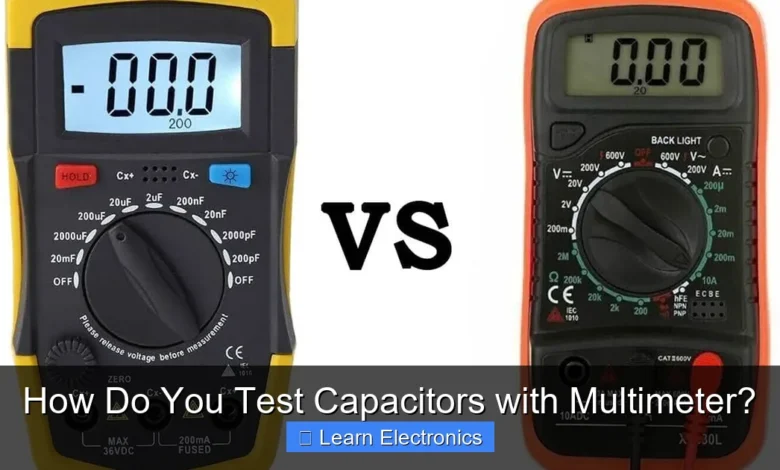
Does my multimeter need a special setting to test capacitors?
Yes, for precise measurements when you test capacitors with a multimeter, you’ll want a dedicated capacitance (usually marked with µF, nF, or pF) setting. This allows your meter to directly display the component’s capacitance value.
What’s the quickest way to check a capacitor’s basic health if I don’t have a capacitance setting?
You can use your multimeter’s resistance (ohms) setting to get a basic health check. A good capacitor will show a momentary drop in resistance as it charges from the meter’s voltage, then gradually increase until it reads ‘OL’ (open loop).
Do I always need to remove the capacitor from the circuit to test it effectively?
For the most accurate and reliable results when you test capacitors with a multimeter, it’s always best to desolder and remove them from the circuit. This prevents other components from influencing your readings and ensures you’re measuring only the capacitor itself.
📑 Table of Contents
Understanding Capacitors and Their Function
Before diving into the testing process, it’s vital to understand what a capacitor is and its role in a circuit. Capacitors are passive electronic components that store electrical energy in an electric field. They consist of two conductive plates separated by a dielectric (insulating) material. Their ability to store charge makes them indispensable for tasks such as filtering power supply ripple, coupling or decoupling signals, timing, and energy storage in various applications.
Capacitors come in different types, each with specific characteristics:
- Electrolytic Capacitors: These are polarized, meaning they must be installed correctly with respect to voltage polarity. They offer high capacitance values but can dry out over time, leading to reduced performance or failure.
- Ceramic Capacitors: Non-polarized, small in size, and known for their stability across a wide temperature range. They typically have lower capacitance values.
- Film Capacitors: Also non-polarized, offering good stability and high precision. They are often used in audio circuits and power supplies.
- Tantalum Capacitors: A type of electrolytic capacitor known for their high capacitance-to-volume ratio and excellent stability. They are polarized and sensitive to reverse voltage.
Understanding these types helps in interpreting test results, as different capacitors may exhibit slightly different charging characteristics or failure modes.
Safety First: Precautions Before Capacitor Testing
Working with capacitors, especially large electrolytic ones, can be hazardous due to stored electrical energy. Always prioritize safety before starting any testing procedure.
Discharging Capacitors Safely
Capacitors can retain a dangerous charge even after power to a circuit has been removed. Failure to discharge them can result in a severe electric shock or damage to your multimeter. Follow these steps:
- Turn Off Power: Ensure the device containing the capacitor is completely disconnected from its power source.
- Wait: For smaller capacitors, a few minutes might be enough. For larger ones (above 100µF or high voltage), wait significantly longer or actively discharge them.
- Use a Resistor: The safest method is to use a high-wattage resistor (e.g., 2W, 1kΩ to 10kΩ) connected across the capacitor’s terminals. This allows the charge to dissipate slowly and safely. Be cautious as the resistor might get warm.
- Verify Discharge: After waiting and using a resistor, use your multimeter on a DC voltage setting to confirm the capacitor is fully discharged (reading close to 0V).
General Safety Guidelines
- Always wear appropriate personal protective equipment, such as safety glasses.
- Avoid touching capacitor terminals directly with your hands, especially before verifying discharge.
- Work in a well-lit and organized environment.
- Familiarize yourself with your multimeter’s functions and safety ratings.
Preparing Your Multimeter for Capacitor Testing
A multimeter is a versatile tool, but not all functions are suitable for capacitor testing. Depending on the capacitor’s type and the nature of the fault you’re looking for, you’ll use different settings.
Multimeter Settings for Capacitor Testing
- Capacitance Measurement ( F or nF): Many modern digital multimeters (DMMs) come with a dedicated capacitance function. This is the most accurate way to determine if a capacitor holds its specified value. Look for a symbol resembling a capacitor (two parallel lines, one often curved) or a ‘F’ (Farad) unit.
- Resistance Measurement (Ohms Ω): This function is used to check for shorts, opens, and to observe the charging/discharging characteristic of electrolytic capacitors. Analog multimeters are particularly good for this due to their sweeping needle display. Digital multimeters can also be used, though the reading might stabilize quickly for smaller capacitors.
- Continuity Test: Useful for quickly checking if a capacitor has a dead short. It typically produces a beep if there’s a low resistance path.
Selecting the Right Range
When using the resistance or capacitance function, select a range appropriate for the capacitor you’re testing. For example, if testing a 10µF capacitor, set your DMM to the 20µF or 200µF range. If the range is too low, it will show an overload (OL) or out-of-range reading. If it’s too high, the reading might lack precision.
Step-by-Step Guide to Testing Different Capacitor Types
The method you use to test a capacitor depends on whether your multimeter has a dedicated capacitance function and the type of capacitor being tested.
Testing with a Dedicated Capacitance Function (Most Accurate)
This is the preferred method for measuring the actual capacitance value.
- Discharge the Capacitor: Absolutely essential, as described in the safety section.
- Set Multimeter: Turn your DMM’s dial to the capacitance ( F) setting.
- Select Range: Choose a range higher than the capacitor’s stated value.
- Connect Probes: Connect the multimeter’s red lead to the capacitor’s positive terminal (or either terminal for non-polarized caps) and the black lead to the negative terminal. For polarized capacitors, ensure correct polarity.
- Read Value: The multimeter display will show the capacitance value. Compare this to the value printed on the capacitor. A reading within ±10-20% of the nominal value is usually acceptable, depending on the capacitor’s tolerance. Significant deviations (e.g., 50% lower) indicate a faulty capacitor. An “OL” or “out of range” reading might mean an open circuit.
Testing Capacitors for Shorts and Opens with a Multimeter (Resistance Mode)
This method is useful for quickly identifying obvious faults like shorts or open circuits, especially when a dedicated capacitance function isn’t available or for larger electrolytic capacitors.
For Electrolytic Capacitors (Polarized):
- Discharge First: Crucial for safety.
- Set Multimeter: Turn your DMM’s dial to the highest resistance range (e.g., 2MΩ or 20MΩ).
- Connect Probes: Connect the red probe to the positive (+) terminal and the black probe to the negative (-) terminal.
- Observe Reading:
- Initially, the display should show a low resistance value (as the capacitor charges from the multimeter’s internal battery).
- As the capacitor charges, the resistance reading should slowly increase towards infinity (OL on most DMMs). This “sweep” indicates the capacitor is charging and is likely good.
- If the reading immediately shows very low resistance (near 0Ω) and stays there, the capacitor is likely shorted.
- If the reading immediately shows “OL” or infinity and stays there, the capacitor is likely open (completely failed internally).
- For an analog multimeter, the needle will sweep from low resistance towards infinity and then settle.
- Reverse Probes (Optional but recommended for thorough check): Disconnect, discharge again, then reconnect with reversed polarity. The same charging behavior (low resistance rising to OL) should be observed.
For Ceramic, Film, and Non-Polarized Capacitors (Smaller Values):
Due to their very small capacitance and rapid charging, digital multimeters on resistance mode may only show “OL” or a brief fluctuation before settling to “OL.” This is generally normal if they are good. To properly test these smaller capacitors, a dedicated capacitance function is almost always necessary.
- If a short is present, the multimeter will read 0Ω (or near 0Ω) immediately.
- An open capacitor will immediately read “OL.”
Interpreting Multimeter Readings
Understanding what your multimeter tells you is key to effective troubleshooting.
What a “Good” Capacitor Looks Like
- With Capacitance Function: The reading will be close to the marked value on the capacitor, within its specified tolerance (e.g., ±10% or ±20%).
- With Resistance Function (for Electrolytics): The multimeter will show a charging characteristic. The resistance starts low and gradually increases towards infinity (OL) as the capacitor charges.
- For Non-Polarized (Resistance): An immediate “OL” reading is usually normal, indicating no short and typically not an open, but a true capacitance value test is best.
Identifying Faulty Capacitors
- Shorted Capacitor:
- Resistance Mode: Reads very low resistance (near 0Ω) immediately and stays there.
- Capacitance Mode: Reads 0 F or a very erratic, low number.
- Continuity Mode: Beeps continuously.
A shorted capacitor allows current to bypass other components, potentially damaging the circuit.
- Open Capacitor:
- Resistance Mode: Reads “OL” (overload) or infinity immediately and stays there, with no charging characteristic.
- Capacitance Mode: Reads “OL” or 0 F.
An open capacitor acts like a break in the circuit, preventing current flow where it’s needed.
- Leaky Capacitor (Electrolytic):
- Resistance Mode: Shows a charging characteristic, but settles at a finite resistance value (not infinity/OL) after charging. This indicates current leakage through the dielectric.
- Capacitance Mode: May still show a value close to nominal, but performance in a circuit will be compromised.
This is common in older electrolytic capacitors where the electrolyte has dried out or degraded.
- Degraded Capacitance (Out of Tolerance):
- Capacitance Mode: Reads a significantly lower value than the marked capacitance, but not zero.
Even if not completely shorted or open, a capacitor that has lost a significant portion of its capacitance will not perform its function correctly.
Common Issues and Troubleshooting
Faulty capacitors are a common cause of electronic device failures. Here’s how to approach common issues related to capacitor failure:
Signs of Physical Damage
Always inspect capacitors visually before testing. Look for:
- Bulging Tops: Especially common in electrolytic capacitors, indicating internal pressure build-up.
- Leaking Electrolyte: A brownish crust or residue around the base of the capacitor.
- Burn Marks: Discoloration on the capacitor body or surrounding PCB.
- Cracked Casings: More common in ceramic or film capacitors.
Any of these signs strongly suggests a failed capacitor, even if it passes a basic multimeter test.
Troubleshooting Tips
- Test In-Circuit vs. Out-of-Circuit: For the most accurate results, it’s always best to desolder and test capacitors out of circuit. Other components connected in parallel can skew your multimeter readings.
- Compare with a Known Good Capacitor: If you’re unsure about your readings, test a new capacitor of the same value. This provides a baseline for comparison.
- Consider ESR (Equivalent Series Resistance): While a standard multimeter doesn’t measure ESR, it’s a critical parameter for electrolytic capacitors, especially in switching power supplies. A high ESR can cause circuit malfunction even if the capacitance value is acceptable. Specialized ESR meters are available for this purpose.
- Temperature Sensitivity: Some capacitors, particularly electrolytics, can exhibit different behaviors at various temperatures. If a device fails intermittently, try cooling or gently heating suspicious capacitors to see if it affects their performance.
Testing capacitors with a multimeter is an invaluable skill for diagnosing circuit problems and ensuring the longevity of your electronic devices. By following safe practices, understanding your multimeter’s functions, and knowing how to interpret the readings, you can confidently identify faulty components. Remember that while a multimeter provides crucial insights into a capacitor’s health, visual inspection and, in some cases, specialized equipment like an ESR meter, can offer an even more complete picture. With practice, this process will become second nature, empowering you to maintain and repair a wide array of electronics effectively.
Frequently Asked Questions
How do I test a capacitor with a multimeter for basic functionality?
First, ensure the capacitor is fully discharged to avoid damaging your multimeter or yourself. Then, set your multimeter to a high resistance (ohms) range and connect the probes across the capacitor terminals. A good capacitor will initially show a low resistance reading that gradually increases to infinity as it charges from the multimeter’s internal battery.
What multimeter settings should I use to test a capacitor?
For a basic “good/bad” check, you should typically use the resistance (ohms, Ω) setting on your multimeter, starting with a high range like 1MΩ. Some more advanced digital multimeters offer a dedicated capacitance (F) measurement function, which provides a more accurate reading of the capacitor’s actual Farad value. Always refer to your multimeter’s manual for specific instructions on using its capacitance mode.
What does it mean if my multimeter shows a continuous short or open circuit when testing a capacitor?
If your multimeter continuously shows a very low resistance (near zero ohms) and doesn’t change, the capacitor is likely shorted internally. Conversely, if it immediately shows infinite resistance and never drops, the capacitor is likely open or completely dead. A healthy capacitor should display a brief low resistance, then steadily rise to infinity as it charges.
Can I test a capacitor’s capacitance value accurately with a standard multimeter?
Most basic multimeters are limited to performing a simple resistance test to determine if a capacitor is generally functional or completely failed. For an accurate measurement of a capacitor’s actual capacitance value in Farads, you need a multimeter equipped with a dedicated capacitance (F) measurement function. Otherwise, a specialized capacitance meter is required for precise readings.
As an Amazon Associate, I earn commission from qualifying purchases.


