How do I Test a Diode? You test a diode primarily by using a digital multimeter (DMM) in its diode test mode, checking its forward voltage drop and ensuring it blocks current in reverse. Mastering this technique is fundamental for anyone working with electronic circuits, allowing you to quickly diagnose component failures.
Understanding the proper practice of checking diodes is crucial for troubleshooting and repair, ensuring the smooth operation of various electronic devices. This straightforward approach provides immediate insight into a diode’s health.
Quick Answers to Common Questions
What’s the simplest way to test a diode?
The easiest method to test a diode is by using a digital multimeter set to its dedicated “diode test” function. This mode provides a small voltage across the diode and displays its forward voltage drop.
What are the expected readings for a good diode?
When testing a diode, a healthy one will show a voltage drop (typically 0.2V to 0.7V) in the forward direction and display “OL” (Open Loop) or “1” (over range) when connected in reverse bias. This clear asymmetry indicates it’s working properly.
Can I still test a diode if my multimeter lacks a diode function?
Absolutely! You can still test a diode using your multimeter’s resistance setting. A functional diode will exhibit low resistance in one direction and extremely high (or infinite) resistance when you reverse the probes, confirming its one-way conductivity.
📑 Table of Contents
Understanding Diodes and Their Function
Before diving into the practical steps of testing, it’s essential to understand what a diode is and how it functions. A diode is a two-terminal semiconductor device that acts as a one-way valve for electric current. It allows current to flow easily in one direction (forward bias) and largely blocks current in the opposite direction (reverse bias).
- Forward Bias: When a positive voltage is applied to the anode and a negative voltage to the cathode, the diode conducts electricity. There’s a small voltage drop across the diode (typically 0.6-0.7V for silicon, 0.2-0.3V for germanium, and up to 1.5-3.5V for LEDs).
- Reverse Bias: When a negative voltage is applied to the anode and a positive voltage to the cathode, the diode blocks current. Ideally, no current should flow, though a very small leakage current might exist in real-world diodes. If the reverse voltage exceeds the diode’s breakdown voltage, it will conduct heavily, often leading to permanent damage.
Knowing these basic principles helps immensely in interpreting the readings you get during the testing process.
Essential Tools for Diode Testing
To accurately evaluate diode functionality, you’ll need the right tools. The most common and effective tool for this task is a digital multimeter.
Digital Multimeter (DMM)
A DMM is indispensable for most electronic troubleshooting, and its diode test mode is specifically designed for checking diodes. This mode typically applies a small voltage (usually around 2-3V) across the diode and measures the resulting voltage drop or indicates an open circuit. Many modern DMMs have a dedicated symbol (often a diode symbol) on their selector dial for this function.
Analog Multimeter
While less precise and often less convenient for diode testing compared to a DMM, an analog multimeter can also be used. In its resistance mode (Rx1 or Rx10), an analog meter’s internal battery supplies current through the probes. When testing a diode, you’ll observe different resistance readings depending on the probe orientation. However, because analog meters measure resistance rather than forward voltage drop directly, interpretation can be less intuitive and vary between meters.
Power Supply and Resistor (for advanced checks)
For more advanced testing, especially to confirm specific characteristics like reverse breakdown voltage for Zener diodes or to observe leakage currents, an external variable power supply, a current-limiting resistor, and an additional ammeter might be necessary. This setup allows for precise control over the voltage and current applied to the diode.
The Primary Method: Using a Digital Multimeter for Diode Testing
This is the most common and recommended approach for verifying diode functionality. Always ensure the diode is disconnected from the circuit before testing to avoid false readings from parallel components.
Setting Up Your DMM
- Turn on your digital multimeter.
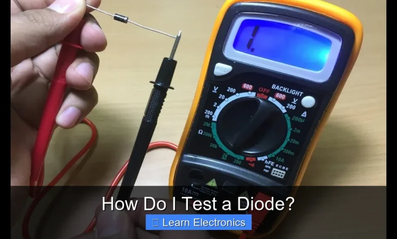
- Rotate the selector dial to the diode test mode. This is usually indicated by a diode symbol (a triangle pointing to a line).
- Insert the red test lead into the VΩmA jack and the black test lead into the COM jack.
Testing in Forward Bias
In forward bias, a good diode should show a specific voltage drop.
- Connect the red (positive) probe to the diode’s anode.
- Connect the black (negative) probe to the diode’s cathode.
- Observe the DMM display.
Expected Reading for a Good Diode: The DMM should display a voltage reading, typically between 0.5V and 0.8V for silicon diodes, or 0.2V and 0.3V for germanium diodes. For LEDs, this drop can be higher (1.5V to 3.5V, and the LED should briefly light up if the test voltage is sufficient). This reading represents the forward voltage drop across the diode.
Testing in Reverse Bias
In reverse bias, a good diode should block current flow.
- Reverse the connections: Connect the black (negative) probe to the diode’s anode.
- Connect the red (positive) probe to the diode’s cathode.
- Observe the DMM display.
Expected Reading for a Good Diode: The DMM should display “OL” (Open Loop) or “1” (indicating an over-range condition, meaning infinite resistance). This shows that the diode is blocking current effectively in the reverse direction.
Interpreting Results: How to Verify Diode Functionality with a Multimeter
The readings you get will tell you the condition of the diode:
- Good Diode: Shows a low voltage drop (e.g., 0.5-0.8V) in forward bias and “OL” in reverse bias.
- Open Diode: Shows “OL” in both forward and reverse bias. This means the diode has an internal break and cannot conduct current in either direction.
- Shorted Diode: Shows approximately 0V or a very low reading (close to a short circuit) in both forward and reverse bias. This means the diode is allowing current to flow in both directions, failing to rectify.
- Leaky Diode: Shows a voltage drop in forward bias but a low resistance or a measurable, though high, voltage in reverse bias instead of “OL.” This indicates partial breakdown in reverse bias, often leading to improper circuit operation.
Common Diode Types and Their Specifics
While the basic testing method applies to most diodes, some types have unique characteristics to consider.
Standard Rectifier Diodes
These are the most common type, used for converting AC to DC. Their forward voltage drop is typically around 0.6-0.7V for silicon. The DMM test is highly effective for these.
Zener Diodes
Zener diodes are designed to operate in reverse breakdown mode, maintaining a stable voltage across their terminals once the Zener voltage is reached. A standard DMM diode test will still show a forward voltage drop (0.6-0.7V) and an “OL” in reverse bias (as long as the DMM’s test voltage is below the Zener voltage). To truly test the Zener voltage, you need an external power supply, a current-limiting resistor, and a voltmeter.
LEDs (Light Emitting Diodes)
LEDs are special diodes that emit light when forward-biased. When checking these diodes with a DMM in diode test mode, if the test voltage is sufficient (usually 2-3V or more, depending on the LED color), the LED should light up faintly, and the DMM will display its forward voltage drop (e.g., 1.5-3.5V). In reverse bias, it should show “OL.”
Schottky Diodes
Schottky diodes have a very low forward voltage drop (typically 0.15-0.45V) compared to standard silicon diodes, making them ideal for high-speed switching applications and power efficiency. Your DMM test should reflect this lower voltage drop in forward bias and “OL” in reverse bias.
Advanced Diode Testing Techniques and Considerations
While a DMM provides a good initial assessment, certain situations or specific diode types might require more detailed evaluation. This offers deeper insights into the diode’s performance and integrity.
In-Circuit vs. Out-of-Circuit Testing
It’s always preferable to test a diode when it’s desoldered or otherwise isolated from the circuit (out-of-circuit). When a diode is still in the circuit (in-circuit), other components connected in parallel can provide alternative paths for the DMM’s test current, leading to misleading or inaccurate readings. For instance, a resistor in parallel with a diode might make a shorted diode appear good, or an open diode appear partially conductive.
Leakage Current Testing
All real-world diodes have a small amount of reverse leakage current, even when correctly reverse-biased below their breakdown voltage. For most applications, this current is negligible. However, in sensitive circuits or high-reliability applications, excessive leakage current can be problematic. Testing for leakage requires a variable DC power supply, a current-limiting resistor, and a sensitive ammeter. You apply a reverse voltage (below the breakdown voltage) and measure the minute current flowing through the diode.
Reverse Breakdown Voltage Test (for Zener Diodes)
As mentioned, Zener diodes are designed for reverse breakdown. To confirm a Zener’s voltage rating, you need a circuit that applies an increasing reverse voltage across the Zener, limited by a series resistor. You then measure the voltage across the Zener as current flows through it. The voltage at which it stabilizes is its Zener voltage.
Checking Diode Arrays and Bridge Rectifiers
For components like diode arrays (multiple diodes in a single package) or bridge rectifiers (four diodes arranged to convert AC to DC), you’ll need to test each individual diode junction separately using the standard DMM method. Consult the component’s datasheet to identify the anode and cathode of each internal diode.
Troubleshooting Diode Failures
Identifying a faulty diode is often a critical step in repairing electronic equipment. Understanding common failure modes and their impact helps in effective troubleshooting.
Identifying Common Failures
- Open Diode: This is a complete failure where the diode behaves like an open circuit in both directions. It won’t allow current flow and will show “OL” on your DMM for both forward and reverse bias.
- Shorted Diode: A shorted diode acts like a direct wire, allowing current to flow freely in both directions. Your DMM will show a very low voltage drop (close to 0V) or continuity in both forward and reverse bias.
- Leaky Diode: A leaky diode allows some current to flow in the reverse direction, even when below its breakdown voltage. This manifests as a reading other than “OL” in reverse bias, typically a high but finite resistance or a very high voltage drop.
Impact on Circuits
- Open Diode: An open diode will prevent current from flowing in the intended direction, often causing the circuit or section it’s part of to stop functioning entirely. For example, in a rectifier circuit, an open diode will result in no output or severely reduced/distorted output.
- Shorted Diode: A shorted diode can cause significant damage. In a rectifier, it might short out the AC source, blow fuses, or damage other components. In protection circuits, a shorted diode offers no protection and might even create a new fault path.
- Leaky Diode: A leaky diode can lead to inefficient operation, excessive heat, and incorrect voltage levels. In power supplies, it might cause ripple or instability. In signal processing, it could introduce distortion.
Replacement Considerations
When replacing a faulty diode, always ensure the new component has equivalent or better specifications, including:
- Forward Voltage (Vf): Though less critical if within a reasonable range.
- Maximum Forward Current (If): The maximum current it can safely handle in forward bias.
- Peak Inverse Voltage (PIV) or Reverse Breakdown Voltage (Vbr): The maximum reverse voltage it can withstand without breaking down.
- Switching Speed: Important for high-frequency applications.
- Package Type: Ensure it fits the existing PCB footprint.
| Diode Type | Typical Forward Voltage Drop (Vf) | Common Applications |
|---|---|---|
| Silicon Diode (Standard) | 0.6V – 0.7V | Rectification, voltage clamping |
| Germanium Diode | 0.2V – 0.3V | RF detectors, low-voltage applications |
| Schottky Diode | 0.15V – 0.45V | Switching power supplies, high-frequency circuits |
| Red LED | 1.8V – 2.2V | Indicators, displays |
| Green LED | 2.0V – 3.1V | Indicators, displays |
| Blue/White LED | 2.8V – 3.5V | Illumination, backlighting |
| Zener Diode | 0.6V – 0.7V (in forward bias) | Voltage regulation (operates in reverse breakdown) |
The values in the table are typical and can vary slightly based on the specific diode model and manufacturer.
Conclusion
Mastering diode testing is a fundamental skill for any electronics enthusiast or professional. By understanding the basic principles of diode operation and effectively utilizing a digital multimeter, you can accurately assess the health of these crucial components. Remember to always test diodes out-of-circuit for the most reliable readings and to interpret your DMM’s display carefully, differentiating between forward voltage drop and reverse bias blocking. With practice, the process becomes second nature, empowering you to troubleshoot and repair electronic circuits with confidence.
Frequently Asked Questions
How do I test a diode using a multimeter’s diode test mode?
Set your multimeter to the diode test function. Connect the red probe to the anode and the black probe to the cathode to check forward bias, noting the voltage drop. Then reverse the probes to check reverse bias; a good diode should show an open circuit or “OL” reading.
What are the expected readings for a good diode?
When forward biased, a good silicon diode should show a voltage drop between 0.5V and 0.9V, while a germanium diode might be 0.2V to 0.4V. In reverse bias, a functional diode should display an “OL” or infinite resistance, indicating no current flow.
What do “open circuit” or “short circuit” readings mean when testing a diode?
An “OL” or infinite reading in both forward and reverse bias indicates an open diode, meaning it’s completely broken and won’t conduct. A very low resistance or near-zero reading in both directions signifies a shorted diode, allowing current to flow both ways when it shouldn’t.
Can I test an LED (Light Emitting Diode) in the same way?
Yes, an LED is a specialized type of diode and can be tested similarly. When connected in forward bias using the diode test mode, a good LED should glow dimly and show a forward voltage drop, typically around 1.5V to 3V depending on its color.
As an Amazon Associate, I earn commission from qualifying purchases.


