Hi Readers in this article we will learn about the boost converter which is a fundamental electronic component in electronics.
For the step-up conversion of applied DC input, we are using the boost converter otherwise known as a step-up converter.
It is a DC-DC converter designed for step-up conversion of the applied dc power.
Note that a Boost converter is also known by the name step-up chopper or a step-up converter.
Don’t confuse by these names, I will be further terming any of the names to represent boosters.
What does a DC Booster do in simple terms?
In the boost converter, the supplied DC input is boosted(term otherwise as increased) to higher than provided DC voltage.
For example, the standard voltage requirements of components are 3v and 5V in mostly used parts.
Say that your motor needs a 5v operating voltage whereas your battery is supplying 3.7v.
In the dc booster you provide 3.7v as an input whereas the output from the dc booster board will be 5v.
So what exactly happens here is the question.
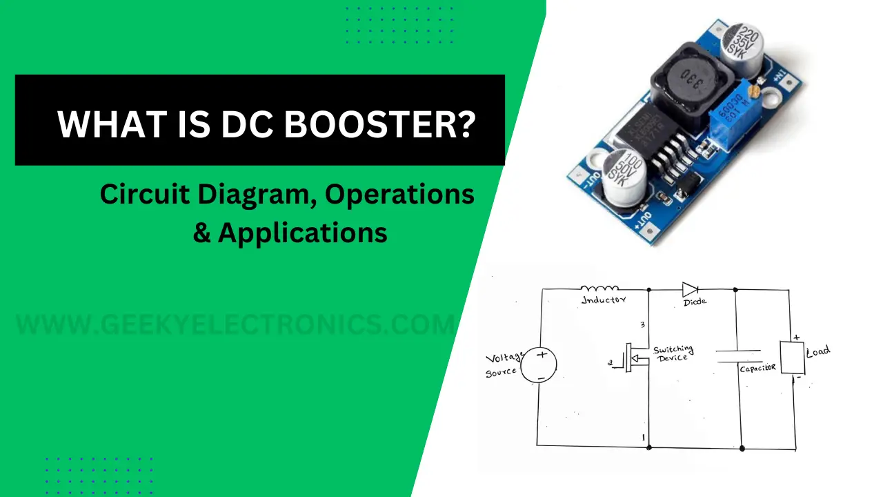
Below are the visuals of a DC-to-DC booster.

If you are an Arduino Project maker then you might have seen the second board.
From the image itself, you can think about the circuit.
Operating Principle of Boost Converter with a Circuit Diagram
The operation principle of the DC boosters or step-up converters lies in the mechanism of storing energy in an inductor.

The voltage drop occurring in an inductor is directly proportional to the change in current flowing throughout the circuit.
The Boost Converter operation occurs in 2 phases.
ON phase and the other one the OFF phase.
While the conversion is during the ON phase, the switch is closed, allows current flow through the inductor while storing energy in its magnetic field.
This happens while the switch opens during the OFF phase, Stored energy is released through the diode(refer the circuit diagram above) into the output capacitor and load.
This cyclic process ensures a higher output voltage.
DC boost converter working theory
This step-up conversion that we saw earlier in the boost converter works with a simple principle
It uses the technique of storing energy in the inductor and then releasing it to the load/device that requires power at a higher voltage.
Here the product of voltage and current results in power.
The most commonly used places of Boost converters are in battery-powered gadgets like electric mosquito bats for example.
An increase in voltage at the output of the boost converter means a decrease in the output current through the circuit.
DC boosters are found in almost every household electronic like radios, TVs, and LED bulbs.
For almost every DC booster that we have now has at least two semiconductors such as a transistor and diode and at least one energy storage element like a capacitor or inductor or both.
Other Switches Used in Boost Converter Circuits
MOSFET, IGBT, and power BJT are used as a switch in boost converter circuits.
Why Thyristors are not used in DC boosters?
Thyristors aren’t used generally for DC to DC converters since other external communication circuits are necessary making entire circuit complex.
Role of Capacitor and Inductors in DC Boosters
The inductor stores energy and helps regulate current, while the output capacitor filters out any ripple voltage, ensuring a smooth and steady output.
Challenges such as high currents, voltage spikes, and electromagnetic interference require careful design considerations and proper protection mechanisms.
The duty cycle, defined as the ratio of ON time to the switching period, determines the voltage conversion ratio. By adjusting the duty cycle, the output voltage can be controlled efficiently.
How Inductor value and duty cycle is calculated?
The duty cycle is calculated based on the desired output voltage and the input voltage. The inductor value is determined by factors like load current and desired ripple current.
It’s important to strike a balance between efficiency, size, and cost while making these choices.
In real applications, a feedback control system is often used to maintain a stable output voltage despite variations in input voltage or load conditions.
This involves using control algorithms to adjust the duty cycle dynamically which is essential for the longevity of the circuit.
Applications of Boost Converter
Battery-Powered Devices
Boost Converters are frequently used in battery-operated devices like smartphones and laptops, where the output voltage needs to be higher than the battery voltage to power various components effectively.
Electric Vehicles
Boost Converters play a pivotal role in electric vehicles by increasing the voltage from the battery to drive the electric motor efficiently, ensuring optimum performance.
Renewable Energy Systems
In solar energy systems, where voltage fluctuations can occur due to changing sunlight intensity, Boost Converters are employed to raise the voltage level before feeding it into the grid or charging batteries.
Power Supply Units
DC boosters find application in power supply units to ensure a stable and regulated output voltage, even when the input voltage varies.
Advantages of DC Boosters
DC boosters offer several advantages, including efficient voltage upconversion, compact size, and the ability to work with a variety of input sources. They contribute significantly to energy-efficient systems and devices.
Future Trends in DC Boost Converter Technology
As technology advances day by day we can expect to see improvements in efficiency on DC boost converter through advanced semiconductors, control algorithms, and integration of smart features to enhance the performance.
Hope now you are aware of the need for DC boosters, you can also read our previous post on Flip flop circuits
As an Amazon Associate, I earn commission from qualifying purchases.


