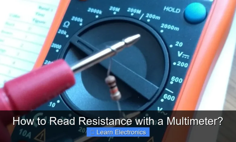
How to Read Resistance with a Multimeter? This essential skill involves setting your multimeter to its Ohms (Ω) function and connecting its probes across the component or circuit you wish to test, providing a direct measurement of electrical resistance. Mastering this technique is fundamental for anyone working with electronics, allowing for accurate troubleshooting and component verification.
Understanding this method is crucial for diagnosing issues, verifying component specifications, and ensuring the proper functioning of electronic circuits. It’s a foundational practice that empowers hobbyists and professionals alike to maintain and repair various devices effectively.
Quick Answers to Common Questions
How do I set my multimeter to read resistance?
To accurately read resistance with a multimeter, first turn its dial to the Ohm (Ω) symbol. If your meter isn’t auto-ranging, start with a higher resistance range than you expect, then adjust down for a more precise reading.
Where do I connect the probes to measure resistance correctly?
You’ll connect the black probe to the “COM” jack and the red probe to the “VΩmA” jack on your multimeter. Make sure the component you’re measuring is disconnected from any power source before touching the probes to its two ends to get an accurate resistance measurement.
What does it mean if my multimeter shows “OL” or “1” when I’m trying to read resistance?
Seeing “OL” (Over Limit) or a “1” on the far left of your display when you read resistance with a multimeter usually indicates that the resistance is higher than your selected range, or there’s an open circuit. Try selecting a much higher resistance range, or double-check your connections to ensure a complete circuit!
📑 Table of Contents
- Understanding Resistance and Your Multimeter
- Essential Preparations Before Measuring Resistance
- Step-by-Step Guide: How to Read Resistance with a Multimeter
- Common Applications and Practical Scenarios
- Tips for Accurate Resistance Measurement
- Understanding Resistor Color Codes for Reading Resistance
- Conclusion
Understanding Resistance and Your Multimeter
Before diving into the practical steps, it’s vital to grasp what electrical resistance is and how a multimeter functions to measure it. This foundational knowledge will make the process of reading resistance more intuitive and meaningful.
What is Electrical Resistance?
Electrical resistance is a fundamental property of a material that opposes the flow of electric current. It’s akin to friction in mechanics; the higher the resistance, the harder it is for current to pass through. Resistance is measured in Ohms (Ω), named after German physicist Georg Simon Ohm. Every conductor, even wires, possesses some resistance, though insulators have very high resistance, effectively blocking current.
Types of Multimeters
Multimeters come in two primary types: digital and analog.
- Digital Multimeters (DMMs): These are the most common type today, featuring an LCD screen that displays readings numerically. DMMs are generally easier to read, more accurate, and often include additional features like auto-ranging.
- Analog Multimeters: These use a needle on a scale to indicate measurements. While still used by some for specific applications due to their ability to show subtle fluctuations, they can be harder to read accurately and are more susceptible to user error, particularly when dealing with resistance scales.
Key Components of a Multimeter for Resistance Measurement
Regardless of type, a multimeter used for resistance measurement will have these key features:
- Rotary Dial/Function Button: Used to select the measurement type (voltage, current, resistance) and range. For resistance, you’ll look for the Ohm symbol (Ω).
- Input Jacks: Typically two or three jacks. The black probe always connects to the “COM” (common) jack. The red probe usually connects to the jack labeled with “VΩmA” or “Ω” for resistance measurements.
- Test Probes: Consisting of a red (positive) and a black (negative) lead, these are used to make contact with the circuit or component being tested.
- Display: For DMMs, this is an LCD screen. For analog meters, it’s a needle and a graduated scale.
Essential Preparations Before Measuring Resistance
Proper preparation is key to accurate and safe resistance measurements. Skipping these steps can lead to incorrect readings, damage to your multimeter, or even personal injury.
Safety First: Precautions
Always prioritize safety. When measuring resistance, ensure the circuit or component is completely powered down and disconnected from any power source. Multimeters inject a small current to measure resistance, and if the component is live, it can damage the meter and give false readings. Additionally, never try to measure resistance on a live circuit.
Choosing the Right Multimeter and Probes
For most general electronics work, a good quality digital multimeter with auto-ranging capability is recommended. Ensure your test probes are in good condition, with no frayed wires or cracked insulation. For very small components, consider probes with fine tips.
Identifying the Ohms (Ω) Setting
Locate the resistance function on your multimeter’s rotary dial. It’s typically indicated by the Greek capital letter Omega (Ω). Many multimeters will also have different ranges (e.g., 200Ω, 2kΩ, 20kΩ, 2MΩ), especially if they are manual-ranging. If your multimeter is auto-ranging, you simply select the Ω function, and the meter will automatically select the best range.
Step-by-Step Guide: How to Read Resistance with a Multimeter
Now, let’s walk through the precise steps involved in reading resistance using your multimeter effectively. This process is straightforward but requires careful execution.
Power Down the Circuit
As stressed before, this is the most critical step. Disconnect the component you want to measure from any power source. If it’s part of a larger circuit, it’s often best to remove the component entirely to avoid measuring parallel resistances in the circuit, which can skew your results.
Connect the Probes
Insert the black test lead into the “COM” jack on your multimeter. Insert the red test lead into the jack labeled “VΩmA” or specifically with the Ohm symbol (Ω). For most measurements, the polarity of the probes doesn’t matter for resistance, but it’s good practice to stick to the standard black-to-negative, red-to-positive convention when possible.
Select the Ohms Range
Turn the rotary dial to the Ohms (Ω) setting. If your multimeter is manual-ranging, start with the highest range available. If you get a reading of “OL” (Over Limit) or “1.” (meaning infinity), it indicates the resistance is higher than the selected range, so you’ll need to move to a higher range. If you get a very low reading or zero, move to a lower range for more precision. With an auto-ranging multimeter, simply select the Ω setting, and it will do the range selection for you.
Take the Measurement
Hold the metal tips of the test probes firmly against the two points of the component or circuit you wish to measure. For a resistor, touch one probe to each end lead. For a wire, touch one probe to each end of the wire. Ensure good contact to get an accurate reading. Avoid touching the metal tips of the probes with your fingers, as your body has its own resistance, which can interfere with the measurement, especially for high-value resistances.
Interpret the Reading
The multimeter’s display will show the resistance value in Ohms (Ω), kilo-Ohms (kΩ), or mega-Ohms (MΩ). A reading close to 0Ω indicates a very low resistance (almost a direct short or a good conductor), while “OL” or “1.” indicates an open circuit or extremely high resistance. Understand the prefixes:
- 1 kΩ = 1,000 Ω
- 1 MΩ = 1,000,000 Ω
For example, if the display shows “4.7 kΩ,” the resistance is 4,700 Ohms.
Common Applications and Practical Scenarios
Knowing how to read resistance with a multimeter opens up many possibilities for troubleshooting and testing electronic components.
Checking Resistors
This is the most direct application. You can verify if a resistor still has its intended value or if it has failed (gone open or short). Compare the measured value to the resistor’s marked value (often indicated by color bands).
Troubleshooting Wires and Cables (Continuity)
The resistance measurement can be used to test for continuity. A “good” wire should have very low resistance (close to 0Ω). If you measure a high resistance or “OL,” it indicates a broken wire or a bad connection. Many multimeters also have a dedicated continuity test function that emits a beep for low resistance, making it quick and convenient.
Testing Switches
You can check if a switch is working correctly. When the switch is “ON,” it should show very low resistance (closed circuit). When “OFF,” it should show very high resistance or “OL” (open circuit). This helps identify faulty switches that are stuck open or closed.
Identifying Component Failures
Many other components, like fuses, heating elements, or even motors (by checking coil resistance), can be tested for functionality using resistance measurements. A blown fuse will show “OL,” while a good one will show very low resistance.
Tips for Accurate Resistance Measurement
Achieving precise resistance readings is crucial for effective diagnosis. Here are some tips to enhance the accuracy of your measurements:
Avoiding User Error
- Clean Contacts: Ensure the component leads and probe tips are clean and free of corrosion. Dirt or oxidation can add spurious resistance to your measurement.
- Firm Contact: Maintain solid contact between the probes and the component. Loose connections can lead to intermittent or inaccurate readings.
- Hands Off: Avoid touching the metal parts of the probes or component leads, especially when measuring high resistances, as your body’s resistance can shunt the component and affect the reading.
The Importance of Auto-Ranging vs. Manual Ranging
While auto-ranging multimeters simplify the process by automatically selecting the correct range, understanding manual ranging is still beneficial. If you use a manual-ranging meter, always start with the highest possible range and work your way down. This prevents false “OL” readings and protects the meter from potential overloads, although resistance measurement is generally low risk for overload.
Understanding Tolerance and Ambient Temperature
Resistors are manufactured with a certain tolerance (e.g., ±5%, ±1%), meaning their actual value can vary slightly from the marked value. Always factor this into your assessment. Additionally, temperature can affect resistance; some materials’ resistance changes with heat. For critical applications, ensure measurements are taken at a stable, room temperature environment.
Measuring Low Resistance (Continuity Test)
For very low resistance values, especially when checking continuity, your multimeter’s internal resistance and the resistance of the test leads themselves can become significant. Most DMMs compensate for this, but for extremely precise low-ohm measurements, specialized low-resistance meters (milliohmmeters) might be needed. For general continuity, the audible beep is usually sufficient.
Understanding Resistor Color Codes for Reading Resistance
When you want to read resistance with a multimeter, it’s often helpful to first know what value to expect by decoding the resistor’s color bands. This provides a quick reference point and helps you verify your multimeter’s reading.
Decoding Standard Resistors
Most axial-lead resistors use a system of colored bands to indicate their resistance value and tolerance. Typically, there are 4 or 5 bands. The first two or three bands represent significant digits, the next band is the multiplier, and the last band indicates tolerance.
Here’s a standard color code chart:
| Color | Digit (Band 1, 2, 3) | Multiplier (Band 3, 4) | Tolerance (Band 4, 5) |
|---|---|---|---|
| Black | 0 | 100 (1) | |
| Brown | 1 | 101 (10) | ±1% |
| Red | 2 | 102 (100) | ±2% |
| Orange | 3 | 103 (1k) | |
| Yellow | 4 | 104 (10k) | |
| Green | 5 | 105 (100k) | ±0.5% |
| Blue | 6 | 106 (1M) | ±0.25% |
| Violet | 7 | 107 (10M) | ±0.1% |
| Gray | 8 | 108 (100M) | ±0.05% |
| White | 9 | 109 (1G) | |
| Gold | 10-1 (0.1) | ±5% | |
| Silver | 10-2 (0.01) | ±10% |
Example: A resistor with bands Red, Violet, Orange, Gold:
- Red (Band 1) = 2
- Violet (Band 2) = 7
- Orange (Band 3, Multiplier) = 103 (1k)
- Gold (Band 4, Tolerance) = ±5%
Value: 27 x 1000 = 27,000 Ω or 27 kΩ with a ±5% tolerance.
Conclusion
Learning how to read resistance with a multimeter is an indispensable skill for anyone delving into the world of electronics. From basic circuit checks to complex troubleshooting, the ability to accurately measure resistance allows you to diagnose problems, verify components, and build reliable electronic projects. By following the straightforward steps outlined, prioritizing safety, and understanding the nuances of your multimeter, you’ll gain the confidence to tackle a wide range of electrical tasks. Practice these techniques regularly, and you’ll soon find yourself adept at interpreting resistance readings and keeping your electronic endeavors on track.
Frequently Asked Questions
How do I set up my multimeter to measure resistance?
To measure resistance, first turn the rotary dial of your multimeter to the Ohm (Ω) setting, which often shares a range with kilohms (kΩ) or megohms (MΩ). Ensure your red probe is inserted into the VΩmA jack and the black probe into the COM (common) jack.
What do the different resistance ranges on a multimeter mean?
The resistance ranges (e.g., 200Ω, 2kΩ, 20kΩ, 2MΩ) on your multimeter’s dial allow you to select the appropriate scale for the component you are testing. Always start with a higher range if you don’t know the approximate resistance, then adjust downwards for a more precise reading. If the reading is too high for the selected range, the multimeter will display “OL” or “1”.
Is it safe to measure resistance in a live circuit with a multimeter?
No, you must never attempt to measure resistance in a live or powered circuit. Doing so can damage your multimeter, blow a fuse, or even create a significant safety hazard for yourself. Always ensure the component or circuit is completely de-energized and isolated from any power source before connecting your multimeter probes.
My multimeter shows “OL” or “1” when measuring resistance. What does that mean?
An “OL” (Over Limit) or “1” displayed on your multimeter screen typically indicates an open circuit or a resistance value that is too high for the selected range. It could mean the component is faulty, the circuit is broken, or you simply need to switch to a higher resistance range on your multimeter’s dial. Double-check your probe connections and the component itself.
How do I correctly interpret the resistance reading on my digital multimeter?
Once you have connected the probes to the component and selected the appropriate range, the digital multimeter will display the resistance value in Ohms (Ω), kilohms (kΩ), or megohms (MΩ). Pay attention to any prefix like ‘k’ or ‘M’ shown on the screen, as this indicates the multiplier for the numerical value. For example, a reading of “2.20 kΩ” means 2,200 Ohms.
As an Amazon Associate, I earn commission from qualifying purchases.


