How to Measure Voltage Drop? You measure voltage drop by comparing the voltage at the source of a circuit to the voltage present at the load, or by directly measuring the potential difference across a specific conductor or component while the circuit is under load. This critical measurement helps diagnose efficiency issues and potential problems within an electrical system. The practice of accurately assessing this electrical phenomenon is fundamental for maintaining optimal performance and reliability in any electronic or electrical application.
Quick Answers to Common Questions
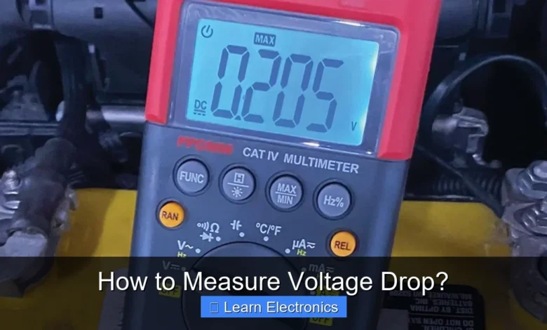
What’s the main tool I need to measure voltage drop?
You’ll primarily need a reliable digital multimeter set to the correct voltage range (AC or DC, depending on your circuit) along with its test leads. Make sure your multimeter is rated for the circuit you’re testing!
How do I physically connect my multimeter to measure voltage drop?
To measure voltage drop across a specific wire, component, or connection, place your multimeter’s leads in parallel across that section while the circuit is active. The reading displayed is your voltage drop.
What’s an acceptable voltage drop, or when should I be concerned?
Generally, an acceptable voltage drop is quite small, often less than 3-5% of the total circuit voltage, depending on the application. If you measure a significant voltage drop, it often indicates excessive resistance and could be a problem.
📑 Table of Contents
Understanding Voltage Drop: What It Is and Why It Matters
Voltage is the electrical potential difference that drives current through a circuit. In an ideal world, the voltage supplied by a power source would remain constant throughout a conductor and arrive at the load without any loss. However, in reality, all conductors have some electrical resistance. As current flows through this resistance, a portion of the electrical energy is converted into heat, resulting in a reduction of voltage available at the load. This reduction is known as voltage drop.
What is Voltage Drop?
Simply put, voltage drop is the decrease in electrical potential along the path of a current-carrying conductor from the source to the load. It’s often expressed in volts (V) or as a percentage of the total source voltage. Imagine water flowing through a pipe; if the pipe is long or narrow, there will be a pressure drop by the time the water reaches the faucet. Electricity behaves similarly, with voltage being analogous to water pressure.
Why is it Important to Measure?
Measuring voltage drop is crucial for several reasons across various applications, from automotive systems to home wiring and industrial machinery:
- Performance Issues: Excessive voltage drop means the load (e.g., a motor, light, or electronic device) is not receiving its full intended voltage. This can lead to underperformance, such as dim lights, slow motors, or malfunctioning electronics.
- Efficiency Loss: The energy lost due to voltage drop is dissipated as heat in the conductor. This represents wasted energy, which can lead to higher electricity bills and reduced overall system efficiency.
- Component Lifespan: Devices operating consistently below their specified voltage can experience premature wear and failure. Conversely, excessive heat generated in conductors due to high drop can degrade insulation and other components.
- Safety Concerns: While typically a performance issue, extreme voltage drop could indicate overloaded circuits or faulty wiring, which might pose a fire hazard in severe cases.
- Troubleshooting: It’s an invaluable diagnostic tool. When a circuit isn’t behaving as expected, voltage drop measurement can quickly pinpoint areas of high resistance, such as corroded terminals, loose connections, or undersized wiring.
Essential Tools for the Job
To accurately perform this measurement, you’ll need a few standard electrical tools. Having the right equipment ensures both accuracy and safety.
Digital Multimeter (DMM)
This is the primary tool for measuring voltage. A good quality digital multimeter is essential. It should be capable of measuring DC voltage (for battery-powered systems and electronics) and/or AC voltage (for household and industrial power) depending on the circuit you’re working on. Ensure it has a sufficiently high input impedance (typically 10 MΩ or more) to avoid loading the circuit and affecting the reading.
Test Leads and Probes
Your DMM will come with test leads, usually one red and one black. Ensure they are in good condition, with no frayed wires or cracked insulation. For automotive or hard-to-reach connections, alligator clips or specialized probe tips can be very useful for securely attaching to test points.
Power Source
The circuit you are testing must be live and operating. This means your battery needs to be charged, or your wall outlet needs to be providing power. The voltage drop will only occur when current is flowing through the conductor.
Load
The device or component that consumes electrical power (e.g., a light bulb, a motor, an appliance). For an accurate measurement, the circuit must be operating under its normal working load. Measuring voltage drop in an unloaded circuit will yield minimal or no drop, as there’s no significant current flow.
Preparing for Accurate Measurement
Before you start connecting your multimeter, a few preparatory steps are crucial for both safety and the accuracy of your readings.
Safety First
- De-energize when possible: While you need the circuit energized to measure voltage drop, initial inspection, wire tracing, and probe attachment should ideally be done with power off if safe and practical. If working on live circuits, extreme caution is necessary.
- Wear appropriate PPE: Safety glasses and insulated gloves are recommended, especially when working with higher voltages or in environments where accidental contact is possible.
- Understand the circuit: Know the voltage levels you expect to encounter. Set your DMM to the appropriate range (e.g., 20V DC, 200V AC) to prevent damage to the meter or inaccurate readings.
Circuit Identification
Identify the specific wires, components, or sections of the circuit where you suspect or want to measure voltage drop. This might involve tracing a wire from a power source to a specific device. Understand the positive/negative (DC) or hot/neutral/ground (AC) paths.
Understanding the Load
Ensure the load is connected and operating as it normally would. For example, if measuring drop to a car’s headlight, turn the headlight on. If measuring drop to a motor, let the motor run.
Equipment Setup
Set your multimeter to the appropriate voltage measurement mode (ACV for alternating current, DCV for direct current). Choose a range that is higher than the expected voltage to avoid over-ranging the meter.
Steps for Measuring Voltage Drop
There are two primary methods for measuring voltage drop, each useful in different scenarios. The first involves taking two separate voltage readings, and the second involves a direct measurement across the component causing the drop. This technique helps pinpoint precisely where the voltage is being lost.
Method 1: Two-Point Measurement and Calculation
This is the most common approach and involves measuring the voltage at two different points in the circuit and then calculating the difference.
- Measure Source Voltage (Vsource):
- Connect your DMM’s red (positive) lead to the positive terminal of your power source (e.g., battery positive, power supply output).
- Connect your DMM’s black (negative) lead to the negative terminal of your power source (e.g., battery negative, power supply ground).
- Record this reading. This is your reference voltage.
- Measure Voltage at the Load (Vload):
- Keeping the circuit operating under load, move your red lead to the point where the positive wire connects to the load (e.g., the positive terminal of a motor, the input terminal of a light bulb).
- Keep your black lead connected to the negative terminal of the power source. Alternatively, if measuring across a specific positive conductor, you would connect the black lead to the negative side of the load itself, ensuring you are still referencing the system ground. For AC circuits, measure between the hot wire at the load and the neutral.
- Record this reading.
- Calculate the Voltage Drop:
Subtract the load voltage from the source voltage:
Voltage Drop = Vsource - VloadExample: If Vsource is 12.6V and Vload is 11.8V, then the voltage drop is 0.8V.
Method 2: Direct Measurement Across the Conductor or Component
This method is often quicker and more precise for identifying voltage loss across a specific wire, connector, or switch.
- Identify the specific segment: Locate the wire, connector, or switch across which you want to measure the drop.
- Connect DMM in parallel with the segment:
- Connect your DMM’s red (positive) lead to the input side of the wire/component you are testing (i.e., closer to the source).
- Connect your DMM’s black (negative) lead to the output side of the wire/component (i.e., closer to the load).
- Ensure the circuit is operating under its normal load.
- Read the Voltage Drop:
The reading on your multimeter will directly display the voltage drop across that specific segment. This is because you are essentially measuring the potential difference between the two ends of the conductor/component.
Example: If you measure directly across a single wire and your DMM reads 0.5V, then that wire has a 0.5V drop.
This direct measurement method is particularly useful for troubleshooting, allowing you to isolate and quantify the drop across individual elements like a corroded fuse holder, a loose connection at a terminal, or an undersized wire.
Interpreting Your Readings and Taking Action
Once you have your voltage drop measurements, the next step is to understand what they mean and decide if corrective action is needed.
What Do the Numbers Mean?
An ideal circuit would have zero voltage drop, but in reality, some drop is always present due to conductor resistance. The key is to ensure it remains within acceptable limits. Generally, a voltage drop of less than 3% of the source voltage is considered acceptable for most applications. Some sensitive electronic circuits or high-power applications might require even tighter tolerances, while others might tolerate slightly more.
- Acceptable Drop (e.g., < 3%): The circuit is likely functioning efficiently, and performance should not be significantly impacted.
- Excessive Drop (e.g., > 3-5%): This indicates a problem. Performance will likely be degraded, efficiency will be reduced, and there might be potential for component damage or safety issues.
Common Causes of Excessive Voltage Drop
If you detect an excessive voltage drop, the culprit usually falls into one of these categories:
- Undersized Wiring: If the wire gauge is too small for the current it needs to carry, its resistance will be too high, leading to significant voltage loss. Longer wires also inherently have more resistance and thus more drop.
- Loose or Corroded Connections: These are very common sources of high resistance. Terminals that are not tightened properly, or connectors that have accumulated rust or oxidation, can add substantial resistance to the circuit.
- Faulty Switches or Relays: Internal resistance within a switch or relay can increase over time, particularly if they are old, dirty, or have been subjected to arcing.
- Damaged Wiring: Kinks, cuts, or internal breaks in a wire can increase its resistance.
- Overloaded Circuits: If too many devices are drawing current from a single circuit, the total current can exceed the wire’s capacity, leading to excessive drop even if the wire size is technically adequate for a single load.
Remedies and Best Practices
Addressing excessive voltage drop typically involves reducing the overall resistance in the affected part of the circuit:
- Use Heavier Gauge Wire: If the wire is undersized for the current and length, replace it with a larger gauge (smaller gauge number) wire.
- Clean and Tighten Connections: Inspect all terminals, connectors, and splices. Clean any corrosion with a wire brush or specialized contact cleaner. Ensure all connections are tight and secure.
- Replace Faulty Components: If a switch, relay, or fuse holder is identified as having high internal resistance, replace it.
- Reduce Circuit Length: While often not practical, shortening wire runs will reduce overall resistance.
- Distribute Load: If a circuit is overloaded, consider adding additional circuits or distributing the load more evenly across existing circuits.
Practical Examples and Data Table
Let’s look at a couple of scenarios where mastering voltage drop measurement can save you time, money, and headaches.
Example 1: Automotive Headlight Circuit
A car owner notices their headlights are dim. They suspect a voltage drop issue.
- Measure Battery Voltage: With the engine off, the battery measures 12.6V.
- Measure Voltage at Headlight: With headlights on (load active), the voltage at the headlight bulb terminal (positive to chassis ground) measures 10.9V.
- Calculate Drop: 12.6V – 10.9V = 1.7V drop.
- Analyze: 1.7V drop on a 12V system is significant (1.7/12.6 ≈ 13.5%). This is excessive and causing the dim headlights. Using the direct measurement method, the technician might then measure across the headlight switch, then across individual wire segments, and finally across the ground path back to the battery, quickly pinpointing a corroded connector in the harness as the culprit.
Example 2: Home Appliance Circuit
A homeowner experiences slow heating from an electric kettle despite it being plugged into a dedicated outlet.
- Measure Outlet Voltage (No Load): With nothing plugged in, the outlet measures 120V AC.
- Measure Outlet Voltage (Under Load): With the kettle plugged in and heating, the voltage at the outlet measures 110V AC.
- Calculate Drop: 120V – 110V = 10V drop.
- Analyze: A 10V drop on a 120V system (10/120 ≈ 8.3%) is very high. This suggests either undersized wiring for the kettle’s wattage, a loose connection at the breaker or outlet, or a problem with the service to the house. Further direct measurements across the circuit breaker, the wire run, and the outlet itself would be necessary.
Table: Recommended Maximum Voltage Drop Percentages
While the 3% rule is a good general guideline, specific applications may have different recommendations.
| Application/Load Type | Recommended Max % Drop | Notes |
|---|---|---|
| General Lighting & Heating | 3% to 5% | Higher drop affects brightness/heat output |
| Motors & Heavy Machinery | 3% | Higher drop causes overheating, reduced torque, motor burnout |
| Sensitive Electronics | 1% to 2% | Critical for proper operation, data integrity |
| Emergency Systems | 1% | High reliability required |
| Branch Circuits (Total) | 3% to 5% | From panel to farthest outlet/fixture |
| Feeders (Total) | 3% | From utility service to main panel |
Conclusion
Mastering voltage drop measurement is an indispensable skill for anyone working with electrical or electronic systems. By understanding what voltage drop is, knowing how to accurately measure it using a multimeter, and being able to interpret the readings, you gain a powerful diagnostic tool. Regular identification and correction of excessive voltage drop not only ensures optimal performance and efficiency but also prolongs the lifespan of components and enhances the overall safety of your electrical installations. Incorporating effective voltage drop measurement into your troubleshooting routine will undoubtedly lead to more reliable and robust circuits.
Frequently Asked Questions
What is voltage drop and why is it important to measure?
Voltage drop is the reduction in electrical potential along a conductor, caused by resistance as current flows through it. Measuring voltage drop is crucial because excessive drop can lead to poor performance, overheating, and damage to electrical components or appliances.
What tools are required to accurately measure voltage drop?
To measure voltage drop, you’ll primarily need a digital multimeter (DMM) capable of measuring DC or AC voltage, depending on your circuit. You’ll also need suitable test leads, and sometimes alligator clips can be helpful for hands-free connections.
How do I practically measure voltage drop across a component or wire?
To measure voltage drop, connect your multimeter’s test leads in parallel across the component or section of wire you want to test while the circuit is active and under load. The multimeter will display the voltage difference between the two points, which is your voltage drop.
What is considered an acceptable level of voltage drop in a circuit?
Acceptable voltage drop varies by application, but generally, a drop of 3% or less for feeder and branch circuits is recommended for optimal performance and efficiency. For sensitive electronics or long cable runs, even smaller drops might be desirable.
What should I do if I detect excessive voltage drop in my system?
If you find excessive voltage drop, it often indicates an issue like undersized wiring, loose connections, or corrosion increasing resistance. You should investigate and rectify these problems, possibly by upgrading wire gauge, tightening connections, or cleaning terminals.
As an Amazon Associate, I earn commission from qualifying purchases.


