To measure resistance on a multimeter, you select the ohms (Ω) setting, connect the leads to the component, and read the displayed value. This fundamental electronic measurement is crucial for diagnosing circuit issues, verifying component specifications, and ensuring proper electrical function.
Understanding this technique allows hobbyists and professionals alike to effectively troubleshoot and repair a wide range of electronic devices. It’s a straightforward process that becomes second nature with a little practice.
Quick Answers to Common Questions
What setting should I select on my multimeter to measure resistance?
To measure resistance on your multimeter, simply turn the dial to the “Ω” (Omega) symbol, which represents Ohms. If your multimeter isn’t auto-ranging, pick a range higher than your expected resistance and adjust down for precision.
When I measure resistance, does it matter which way I connect the probes?
No, when you measure resistance on a multimeter for most passive components like resistors, the polarity doesn’t matter. You’ll get the same Ohm reading whether the red probe is on the left or right!
Why does my multimeter show “OL” or a super high number when I try to measure resistance?
Seeing “OL” (Over Limit) or an extremely high reading usually means the resistance is too high for the selected range, or there’s an open circuit. Double-check your probe contact and try a higher range setting on your multimeter to accurately measure resistance.
📑 Table of Contents
- Understanding Resistance: The Foundation of Electronic Diagnostics
- Types of Multimeters and Their Resistance Functions
- Preparing Your Multimeter for Resistance Measurement
- Step-by-Step: How to Measure Resistance on a Multimeter Safely
- Troubleshooting and Advanced Considerations for Resistance Measurement
- Conclusion
Understanding Resistance: The Foundation of Electronic Diagnostics
Resistance is a fundamental property of an electrical conductor that opposes the flow of electric current. It’s measured in ohms (Ω), named after German physicist Georg Simon Ohm. Every material offers some level of resistance, from nearly zero in superconductors to extremely high values in insulators.
Why is measuring resistance so important?
- Troubleshooting Circuits: Abnormal resistance readings can indicate a short circuit (too low resistance), an open circuit (infinite resistance), or a faulty component.
- Component Verification: You can check if a resistor, wire, or other component matches its specified resistance value.
- Safety: Ensuring proper resistance in grounding wires, for example, is vital for electrical safety.
- Circuit Design: Engineers rely on precise resistance measurements when designing and prototyping new electronic systems.
Ohm’s Law and Resistance
Ohm’s Law describes the relationship between voltage (V), current (I), and resistance (R) in a circuit: V = I × R. This means if you know any two values, you can calculate the third. When you measure resistance directly, you’re getting a key piece of information that helps understand how a circuit will behave under power.
Types of Multimeters and Their Resistance Functions
Before you begin, it’s helpful to know the type of multimeter you’re using, as this will influence the specific steps.
Digital Multimeters (DMMs)
Digital multimeters are the most common type today, featuring an LCD screen that displays readings directly. They are generally more precise and easier to read than analog meters.
- Auto-Ranging DMMs: These multimeters automatically select the correct range for the measurement, making them very user-friendly. You simply select the ohms (Ω) function, and the meter adjusts itself.
- Manual-Ranging DMMs: With these meters, you need to manually select the resistance range (e.g., 200Ω, 2kΩ, 20kΩ, 2MΩ). Always start with a higher range and work your way down if you don’t know the approximate resistance value.
Analog Multimeters
Analog multimeters use a needle to indicate values on a graduated scale. While still effective, reading resistance on an analog meter can be trickier because the resistance scale is often non-linear and runs from right to left (0Ω on the right, infinite on the left). You’ll also need to “zero” the meter before each measurement by shorting the leads and adjusting a knob until the needle reads zero ohms.
Preparing Your Multimeter for Resistance Measurement
Proper setup is critical for accurate and safe resistance readings.
- Power Off the Circuit/Component: This is perhaps the most crucial step. Resistance measurements must always be performed on de-energized circuits. If there’s any voltage present, you could damage your multimeter or get inaccurate readings. If measuring a component, remove it from the circuit entirely if possible.
- Insert Test Leads:
- Plug the black test lead into the “COM” (common) jack.
- Plug the red test lead into the jack labeled for ohms (Ω) or the VΩmA jack, which usually handles voltage, resistance, and current.
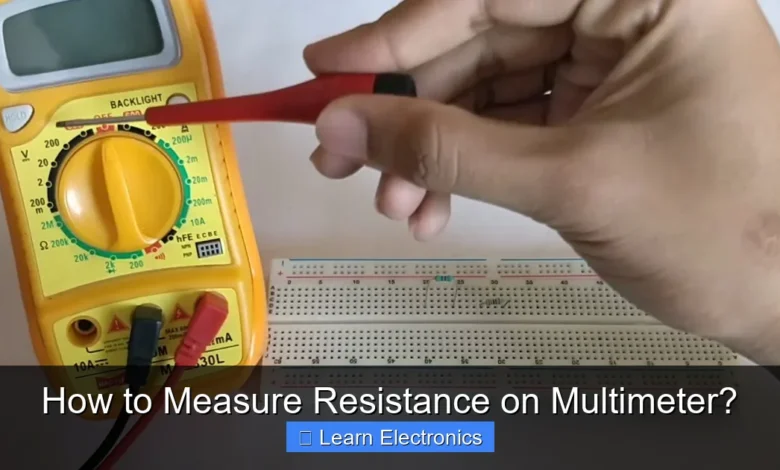
- Select the Ohms (Ω) Function: Turn the multimeter’s rotary dial to the resistance (Ω) symbol. On some multimeters, the Ω symbol might share a setting with other functions, requiring you to press a “Function” or “Select” button to cycle to resistance mode.
- Choose the Right Range (Manual-Ranging DMMs Only): If your multimeter is manual-ranging, select an appropriate range. If you have no idea what the resistance value might be, start with the highest range available (e.g., 2MΩ or 20MΩ) and progressively decrease it until you get a stable reading. If you start too low, the display might show “OL” (overload) or “1” (infinite resistance).
Ensuring Accurate Resistance Readings
- Calibrate (Analog Meters): For analog meters, touch the red and black leads together and adjust the “Ohms Adjust” knob until the needle reads zero on the resistance scale.
- Check Leads: Briefly touch the red and black leads together. Your multimeter should display close to 0 ohms (0.1Ω – 0.5Ω is common for lead resistance). If it shows “OL” or a much higher value, your leads might be faulty.
Step-by-Step: How to Measure Resistance on a Multimeter Safely
Once your multimeter is prepared and the circuit is de-energized, you’re ready to take the measurement.
- Isolate the Component: For the most accurate reading, it’s best to remove the component (e.g., a resistor, bulb, or switch) from the circuit entirely. If you measure resistance while the component is still in the circuit, other parallel paths in the circuit can skew your reading. If complete isolation isn’t possible, ensure power is off and all other components that might create a parallel path are temporarily disconnected or in an open state.
- Connect the Test Leads: Touch one test lead to one end of the component and the other test lead to the other end. For non-polarized components like resistors, it doesn’t matter which lead goes to which end. For polarized components (though resistance measurement is less common for these), simply ensure good contact.
- Read the Display:
- Digital Multimeter: The resistance value will appear on the LCD screen. Pay attention to the units (Ω, kΩ, MΩ) displayed, as these indicate the magnitude (ohms, kilohms, megohms). For example, “10.5 kΩ” means 10,500 ohms.
- Analog Multimeter: Read the resistance scale (often the top scale, non-linear, and decreasing from left to right).
- Document the Reading: Note down the measured value for future reference or comparison.
Interpreting Common Resistance Readings
- 0 Ohms (or very close to it): Indicates a short circuit or a very good conductor (like a wire).
- “OL” or “1” (Overload/Infinite): Means an open circuit or resistance too high for the selected range. This often indicates a break in a wire or a blown fuse.
- Stable Value: A consistent numerical reading indicates the actual resistance of the component.
Troubleshooting and Advanced Considerations for Resistance Measurement
Even with correct setup, challenges can arise. Here’s how to address them and explore more advanced uses.
Common Issues and Troubleshooting Tips
- Inaccurate Readings in Circuit: As mentioned, measuring resistance on a component still in a circuit can lead to misleading values due to parallel paths. Always try to isolate the component.
- Human Body Resistance: Touching both metal probes while measuring can add your body’s resistance to the circuit, especially for high-value resistors. Avoid touching the metal tips of the probes simultaneously when measuring.
- Battery Issues: A low battery in your multimeter can cause inaccurate readings or display errors. Replace the battery if suspect.
- Dirty Probes/Contacts: Poor contact between the probes and the component can lead to fluctuating or incorrect readings. Ensure clean, firm connections.
Practical Applications of Resistance Measurement
Beyond basic component checks, this method offers deeper diagnostic capabilities:
- Checking Wires and Cables: Measure resistance from end to end to check for breaks (should be near 0Ω). Measure between wires to check for shorts (should be infinite).
- Testing Switches: A switch should show near 0Ω when closed and “OL” when open.
- Verifying Fuses: A good fuse should show near 0Ω. A blown fuse will show “OL”.
- Checking Speaker Coils: Measure the resistance of a speaker coil to determine if it’s open or shorted.
- Thermistors and Sensors: These components have resistance that changes with temperature or other physical properties. Measuring their resistance helps verify their function at different conditions.
Data Table: Common Resistance Ranges & Interpretation
Understanding the scales on your multimeter is crucial, especially for manual-ranging devices. Here’s a general guide:
| Multimeter Range Setting | Maximum Resistance Measured (Approx.) | Typical Use Cases | Interpretation if “OL” |
|---|---|---|---|
| 200 Ω | 0.1 – 199.9 Ω | Wires, low-value resistors, fuses, short checks | Resistance > 199.9 Ω |
| 2 kΩ (2000 Ω) | 0.001 – 1.999 kΩ | Medium-value resistors, small motors | Resistance > 1.999 kΩ |
| 20 kΩ | 0.01 – 19.99 kΩ | Resistors, some sensors, potentiometer checks | Resistance > 19.99 kΩ |
| 200 kΩ | 0.1 – 199.9 kΩ | High-value resistors, circuit path checks | Resistance > 199.9 kΩ |
| 2 MΩ (2000 kΩ) | 0.001 – 1.999 MΩ | Very high-value resistors, insulation checks | Resistance > 1.999 MΩ |
| 20 MΩ | 0.01 – 19.99 MΩ | Insulation resistance, open circuit checks | Resistance > 19.99 MΩ |
Note: “OL” (Overload) or “1” on the display means the resistance is higher than the selected range. If this occurs on a manual-ranging meter, switch to a higher range.
Conclusion
Mastering the art of resistance measurement with a multimeter is an indispensable skill for anyone working with electronics. From troubleshooting simple circuits to validating complex component values, the ability to accurately gauge ohmic values provides critical insights into the health and functionality of electrical systems.
By following the correct procedures—powering off, setting the meter correctly, isolating components, and interpreting readings—you can confidently use this technique to diagnose problems and ensure your projects or repairs are successful. Practice makes perfect, so grab your multimeter and start exploring the world of resistance today!
Frequently Asked Questions
How do I prepare my multimeter to measure resistance?
To measure resistance, first insert the black probe into the COM jack and the red probe into the VΩmA jack. Then, turn the rotary dial to the Omega (Ω) symbol, which represents resistance, selecting an appropriate range if your multimeter is not auto-ranging.
What do the different Ohm (Ω) ranges on a multimeter mean when measuring resistance?
The Ohm (Ω) symbol indicates the resistance measurement function. If your multimeter is manual-ranging, you need to select a range (e.g., 200Ω, 2kΩ, 20kΩ) that is higher than the expected resistance value to get an accurate reading. Auto-ranging multimeters will automatically select the best range for you.
Why does my multimeter show “OL” or infinite when I try to measure resistance?
“OL” (Over Limit) or an infinite symbol typically means the resistance value is too high for the selected range or there is an open circuit. If you’re measuring a component, ensure good contact with the probes and try selecting a higher resistance range on your multimeter, or verify the component isn’t actually open.
Are there any important safety considerations when using a multimeter to measure resistance?
Yes, always ensure the circuit or component you are testing is completely de-energized and disconnected from any power source before measuring resistance. Measuring resistance on a live circuit can damage your multimeter and pose a safety risk. Additionally, avoid touching the metal tips of the probes simultaneously while testing, as your body’s resistance can affect the reading.
How do I accurately measure the resistance of a component within a circuit?
For the most accurate measurement of a component’s resistance, it is best to remove at least one lead of the component from the circuit. This prevents other parallel components or circuit paths from influencing your multimeter’s resistance reading. Once isolated, touch the multimeter probes to each end of the component to get its individual resistance value.
As an Amazon Associate, I earn commission from qualifying purchases.


