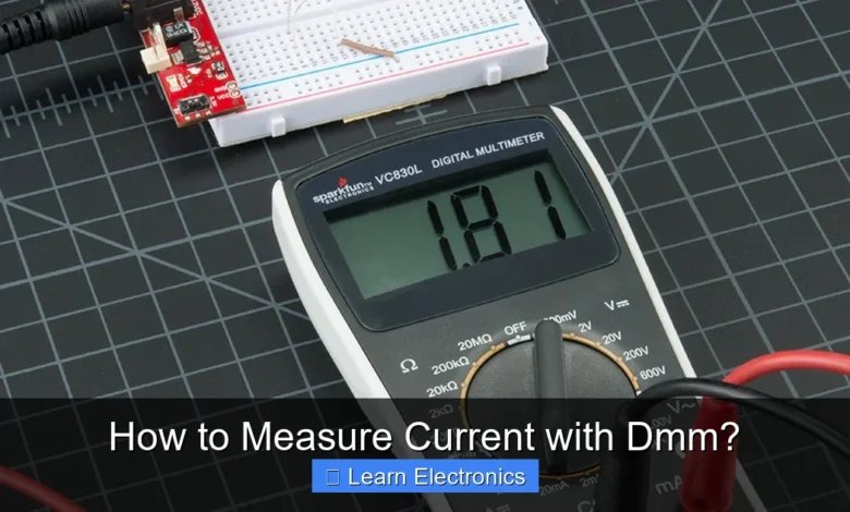
How to Measure Current with DMM? You do so by placing the Digital Multimeter (DMM) in series with the circuit you wish to measure, effectively breaking the circuit and allowing the current to flow through the meter. This technique is fundamental in electronics troubleshooting and design, providing crucial insights into circuit behavior.
Understanding this method is essential for anyone working with electrical circuits, as improper application can lead to damaged equipment or, more critically, personal injury. It allows you to verify component operation, diagnose faults, and ensure circuits are drawing the expected amount of power.
Quick Answers to Common Questions
How do I safely connect my DMM to measure current?
To measure current with your DMM, you must always connect it in series with the circuit you want to test. This means breaking the circuit and inserting the DMM so the current flows *through* it.
Which setting on my DMM should I use to measure current?
You’ll want to select the “A” (Amps), “mA” (milliamps), or “µA” (microamps) setting on your DMM’s dial, depending on the expected current magnitude. Remember to also plug your red lead into the correct “A” or “mA/µA” input jack!
What’s the biggest mistake when trying to measure current with a DMM?
The most common and dangerous mistake is connecting your DMM in parallel across a voltage source, which acts like a short circuit. This usually blows your DMM’s internal fuse or could even damage your circuit, so always connect in series!
📑 Table of Contents
Understanding Current and Why We Measure It
Electric current is one of the foundational concepts in electronics, and its precise measurement is critical for both safety and functionality. Before diving into the practical steps, it’s important to grasp what current is and why its accurate measurement is indispensable.
What is Electric Current?
Electric current, often denoted by the symbol ‘I’, is the rate of flow of electric charge past a point or region. In simple terms, it’s the movement of electrons through a conductor, such as a wire. It is measured in amperes (A), with smaller units like milliamperes (mA) and microamperes (µA) commonly used for electronic circuits. Unlike voltage, which is measured across components, current flows through components and wires.
Importance of Current Measurement
Measuring current serves several vital purposes:
- Troubleshooting: An abnormally high or low current draw can indicate a short circuit, an open circuit, or a faulty component.
- Component Protection: Many electronic components have maximum current ratings. Measuring current helps ensure these ratings are not exceeded, preventing damage or premature failure.
- Power Consumption: Knowing the current draw of a device allows you to calculate its power consumption (Power = Voltage x Current), which is essential for battery life estimations or power supply sizing.
- Circuit Design and Verification: Engineers measure current to verify that their circuit designs are functioning as intended and that current distribution meets specifications.
Essential Tools and Safety Precautions
Before you begin the process of current measurement, you need the right tools and a strong understanding of safety protocols. Ignoring safety can lead to serious injury or damage to your equipment.
The Digital Multimeter (DMM)
A Digital Multimeter (DMM) is an indispensable tool for any electronics enthusiast or professional. It’s a versatile electronic measuring instrument that can measure voltage, resistance, and continuity, in addition to current. For current measurement, a DMM typically has multiple input jacks and a rotary dial to select the desired function and range.
- Input Jacks: Most DMMs have a common (COM) jack, a voltage/resistance/diode jack (VΩmA), and a dedicated high-current jack (10A or 20A).
- Rotary Dial: This allows you to switch between AC and DC current measurements and select appropriate ranges (e.g., mA, A).
- Fuses: DMMs often contain internal fuses to protect the meter itself, especially on the current measurement settings. These fuses are designed to blow if excessive current is applied, preventing damage to the meter.
Safety First When Measuring Current with DMM
Measuring current is inherently more risky than measuring voltage because it requires you to break the circuit and insert the meter in series. This means the full circuit current will flow through your DMM. Always prioritize safety:
- Never Measure Current Across a Voltage Source: Connecting a DMM in parallel with a voltage source (like a battery or power supply) while in current mode will create a short circuit through the DMM, potentially damaging the meter, blowing its fuse, or causing an arc flash. Current mode is for series connections only.
- Turn Off Power: Always de-energize the circuit before connecting or disconnecting your DMM. This prevents accidental shorts and protects you from electric shock.
- Use the Correct Range: If you’re unsure of the current value, start with the highest current range on your DMM and work your way down. This prevents overloading the meter and blowing its fuse.
- Check DMM Fuses: If your DMM stops reading current, the internal fuse is likely blown. Replace it with a fuse of the correct rating.
- Insulated Leads: Ensure your test leads are in good condition, without any frayed wires or damaged insulation.
- Wear Safety Glasses: In case of an arc or component failure, eye protection is crucial.
Preparing Your DMM for Current Measurement
Proper setup of your DMM is crucial for accurate and safe current measurement. Rushing this step can lead to incorrect readings or damage to your meter.
Selecting the Correct Mode and Range
The first step is to configure your DMM for current measurement. Most DMMs will have separate settings for AC (alternating current) and DC (direct current) amps. Ensure you select the correct type for your circuit:
- DC Amps (A= or DCA): Used for battery-powered circuits, DC power supplies, and most electronic circuits.
- AC Amps (A~ or ACA): Used for household wiring, AC motors, and other AC powered devices.
Once you’ve selected AC or DC current, choose an appropriate range. DMMs typically offer ranges such as 10A (or 20A), 400mA, 40mA, 4mA, and 400µA. As mentioned earlier, if you’re unsure of the expected current, start with the highest range (e.g., 10A) and then adjust downwards for a more precise reading. This prevents overloading the meter.
Proper Lead Connection
Connecting the test leads correctly is critical when attempting to measure current with DMM:
- Black Lead: Always connect the black test lead to the DMM’s “COM” (common) jack.
- Red Lead:
- For measuring high currents (typically up to 10A or 20A), plug the red lead into the dedicated high-current input jack, often labeled “10A”, “20A”, or “A”.
- For measuring small currents (milliamperes or microamperes), plug the red lead into the “mA” or “µA” jack. This jack is often combined with the voltage and resistance jack (VΩmA).
Double-check these connections before proceeding to ensure your meter is ready and correctly configured.
How to Measure Current with a DMM: The Step-by-Step Process
Now that your DMM is prepared and safety precautions are in mind, let’s go through the practical steps to measure current effectively. Remember, current measurement always requires the meter to be inserted in series within the circuit path.
Breaking the Circuit (Series Connection is Key)
This is the most crucial difference between measuring current and other electrical parameters. To measure the current flowing through a specific component or section of a circuit, you must break the circuit at that point and insert the DMM in series, essentially making the DMM part of the circuit. The current will then flow through the DMM’s internal shunt resistor.
- Identify the Measurement Point: Locate the component or section of the circuit through which you want to measure current.
- De-energize the Circuit: Crucially, turn off the power to the circuit before making any connections. This protects you and your equipment.
- Break the Circuit: Physically disconnect one side of the component or wire at the point where you want to measure. For example, if measuring current through a resistor, disconnect one lead of the resistor from the rest of the circuit.
- Connect the DMM in Series:
- Connect one DMM test lead (typically the red lead, though polarity doesn’t matter for initial connection in DC) to the disconnected end of the component/wire.
- Connect the other DMM test lead (black lead) to the point in the circuit where you broke the connection.
Essentially, the current must flow into one DMM lead and out of the other DMM lead to complete the circuit.
Taking the Reading
- Apply Power: Once the DMM is properly connected in series and you’ve double-checked all connections, re-apply power to the circuit.
- Observe the Display: The DMM display will show the current flowing through the circuit at that point.
- Adjust Range (if necessary): If the reading is “OL” (overload) or very close to the maximum of your chosen range, immediately remove power, switch to a higher current range, and re-apply power. If the reading is very small and lacks resolution, remove power, switch to a lower current range, and re-apply power.
- Note Polarity (for DC): For DC current, if the reading shows a negative sign, it simply means your test leads are connected with reverse polarity relative to the actual current flow. The magnitude is still correct.
Interpreting the Results
Once you have a stable reading, interpret it in the context of your circuit. Compare the measured current to the expected current (calculated from Ohm’s Law or component specifications). Deviations can indicate a problem:
- Higher than Expected Current: Could indicate a short circuit, a faulty component drawing excessive current, or an incorrect load.
- Lower than Expected Current (or Zero): Could indicate an open circuit, a blown fuse, a faulty component, or an incorrect power supply.
Common Pitfalls and Troubleshooting
Even with careful preparation, issues can arise when measuring current. Knowing common pitfalls can help you diagnose problems quickly.
Blown Fuses
The most common issue when measuring current is a blown fuse within the DMM. This happens when the current flowing through the meter exceeds the rating of the fuse in the selected current range. If your DMM suddenly reads “0.00” or “OL” when you expect a current, and it works fine on voltage or resistance, it’s highly likely the current fuse is blown. To fix this, you must:
- De-energize the Circuit: Always turn off power.
- Turn Off DMM: Power down your multimeter.
- Open DMM Casing: Refer to your DMM’s manual for instructions on how to safely open the case and access the fuse compartment.
- Replace Fuse: Replace the blown fuse with a new one of the exact same type and rating (e.g., 10A, fast-acting). Never use a fuse with a higher rating or bypass the fuse, as this removes the meter’s protection.
- Reassemble DMM: Close the casing securely before reuse.
Incorrect Range Selection
If your DMM displays “OL” (overload) or a very low, fluctuating number:
- “OL” or Blank: You’ve likely exceeded the selected range. Switch to a higher current range (e.g., from mA to A).
- Very Low Reading: If the reading is too small to be accurate, switch to a lower current range (e.g., from A to mA or µA) for better resolution.
Always remember to remove power from the circuit before changing ranges, especially when moving to a lower range where the risk of blowing a fuse is higher.
Open Circuit Reading
If your DMM reads “0.00” when you expect current to flow, confirm that your DMM is indeed completing the circuit. An open circuit (a break in the path) will result in no current flow. Check your connections, the DMM’s leads, and the circuit itself for any disconnections or faulty components that might be preventing current flow.
Practical Applications and Advanced Tips
Mastering current measurement opens up a world of diagnostic possibilities. Here are some practical applications and tips to enhance your skills.
Measuring Current in Different Circuits (DC vs. AC)
The fundamental principle of connecting the DMM in series remains the same, but there are nuances:
- DC Current: Polarity matters for display (negative sign if leads are reversed), but the magnitude is always positive. Used in battery-powered devices, automotive electronics, and most microcontrollers.
- AC Current: Polarity rapidly changes, so DMMs measure the RMS (Root Mean Square) value, which is the effective DC equivalent. Polarity of leads does not affect the reading. Used for mains power, transformers, and AC motors. Ensure your DMM is set to the AC current (A~) mode. Some DMMs also offer a “True RMS” feature, which provides more accurate readings for non-sinusoidal AC waveforms.
Using Clamp Meters (Brief Mention)
While this post focuses on DMMs, it’s worth noting that for higher AC currents, a clamp meter offers a non-contact method. Instead of breaking the circuit, you simply clamp the meter’s jaws around one of the current-carrying wires. This is much safer and faster for certain applications, especially in industrial or residential wiring. Most clamp meters only measure AC current, though some advanced models can also measure DC current via specialized Hall effect sensors.
Data Table: DMM Current Measurement Ranges
This table illustrates typical current ranges you might find on a standard DMM and their corresponding applications.
| DMM Range Setting | Typical Application | Maximum Current |
|---|---|---|
| µA (Microamperes) | Low-power sensors, quiescent current of sleep modes | Typically 400µA |
| mA (Milliamperes) | LEDs, small motors, integrated circuits, general electronics | Typically 400mA |
| A (Amperes) Low | Medium-power circuits, small appliances | Typically 4A |
| A (Amperes) High | Power supplies, automotive systems, high-power loads | Typically 10A or 20A |
Always consult your DMM’s specific manual for its exact range capabilities and limitations.
Conclusion
Measuring current with a DMM is a fundamental skill in electronics, critical for diagnosis, safety, and understanding circuit behavior. By understanding what current is, respecting safety precautions, properly configuring your DMM, and meticulously connecting it in series, you can obtain accurate and valuable measurements. Remember to always de-energize circuits before making connections, use the correct range, and be prepared to replace a blown fuse if necessary. With practice and adherence to these guidelines, you’ll confidently use this indispensable technique to troubleshoot and analyze a wide array of electrical and electronic circuits.
Frequently Asked Questions
How do I safely connect a DMM to measure current?
To safely measure current, you must connect your Digital Multimeter (DMM) in series with the circuit you want to test. This means breaking the circuit and inserting the DMM so that all the current flows through the meter. Ensure you use the correct input jacks on your DMM, typically marked “A” (Amperes) or “mA” (milliamperes) and “COM” (common).
What DMM settings should I use for current measurement?
First, select the appropriate function on your DMM for current measurement, usually marked with “A” for Amperes (AC or DC, depending on your circuit). It’s best practice to start with the highest current range available to avoid overloading the meter and blowing a fuse. Then, if the reading is too low, you can step down to a more sensitive range like milliamperes (mA) or microamperes (µA).
Why must I connect my DMM in series to measure current?
You must connect your DMM in series because current measurement requires the meter to become a part of the circuit, allowing the full current to flow through its internal shunt resistor. Connecting it in parallel would create a short circuit across the component, potentially damaging the circuit, the DMM, or both, as the DMM has very low internal resistance when in current mode.
What are common mistakes to avoid when measuring current with a DMM?
A very common and dangerous mistake is connecting the DMM in parallel across a voltage source or component while it’s in current measurement mode. This effectively creates a short circuit due to the DMM’s low internal resistance, which will blow the DMM’s fuse or even damage the meter and power source. Always ensure the meter is in series and on an appropriate current range before applying power.
As an Amazon Associate, I earn commission from qualifying purchases.


