How to Measure Current by Multimeter? To measure current using a multimeter, you must connect the device in series within the circuit you wish to test, effectively breaking the circuit and routing the current through the multimeter. This method allows the multimeter to act as an ammeter, registering the flow of electrons.
Understanding this technique is fundamental for anyone working with electronics, as it helps diagnose issues, verify component specifications, and ensure proper circuit operation. Mastering the practice of current measurement is crucial for both safety and accuracy.
Quick Answers to Common Questions
Why do I need to connect my multimeter in series when measuring current?
To accurately measure current, your multimeter needs to become a direct part of the circuit’s path, allowing all the electron flow to pass through it. This “series” connection ensures the multimeter sees the actual amount of current moving through that specific point.
Which setting should I choose on my multimeter to measure current?
Look for the ‘A’ symbol, which stands for Amperes (the unit for current), often with a solid line for DC current or a wavy line for AC current. You’ll typically find ranges like mA (milliamps) or A (amps) to select on your multimeter dial before you attempt to measure current.
What’s the biggest mistake people make when trying to measure current?
The most common and potentially dangerous mistake is trying to measure current by connecting your multimeter in parallel across a voltage source, like a battery or an outlet. This effectively creates a short circuit through your meter, which can damage the multimeter or the power source, and even cause a fire!
📑 Table of Contents
Understanding Electrical Current and Your Multimeter
Before diving into the practical steps, it’s essential to grasp what electrical current is and how your multimeter functions to measure it. Current measurement is distinct from voltage or resistance, requiring a different approach.
What is Current (Amperage)?
Electrical current, measured in amperes (A), is the rate of flow of electric charge. Imagine it as the volume of water flowing through a pipe per second. In a circuit, current flows from a higher potential (positive terminal) to a lower potential (negative terminal) in conventional flow, or electrons flow from negative to positive. Unlike voltage, which is measured across components, current is measured through components.
Key Multimeter Settings for Current Measurement
Your multimeter will typically have specific settings for measuring current:
- A (Amperes): For larger currents, usually in the range of Amps.
- mA (Milliamperes): For smaller currents, where 1 mA = 0.001 A. Most common for hobby electronics.
- µA (Microamperes): For very small currents, where 1 µA = 0.000001 A.
It’s crucial to select the correct setting to avoid damaging the multimeter or getting an inaccurate reading. Most multimeters also differentiate between AC (alternating current) and DC (direct current) measurements, indicated by symbols like ~ for AC and — for DC, with three dots or a dashed line below the solid line.
Types of Multimeters for Measuring Current
Multimeters come in various forms, but for current measurement, the key distinction is often between auto-ranging and manual-ranging devices:
- Auto-ranging Multimeters: These automatically select the appropriate range for the measurement, simplifying the process. You usually just select ‘A’, ‘mA’, or ‘μA’ and the meter does the rest.
- Manual-ranging Multimeters: With these, you must manually set the range (e.g., 200mA, 10A) after selecting the measurement type. If you’re unsure of the expected current, always start with the highest range and work your way down to prevent blowing a fuse.
Safety First: Essential Precautions
Measuring current can be risky if not done correctly. Unlike voltage measurement, which is done in parallel, current measurement involves breaking the circuit and placing the multimeter in series. This means the full current of the circuit will pass through your meter. Always prioritize safety.
Never Measure Current Across a Voltage Source
This is the most critical safety rule. Never connect your multimeter probes directly across a battery, power supply, or wall outlet when the multimeter is set to measure current (amps). Doing so will create a short circuit through your multimeter, potentially blowing its internal fuse, damaging the meter, or even causing a fire. Current is measured in series with a load, never in parallel with a voltage source.
Check Multimeter Fuse
Multimeters have internal fuses specifically to protect the device during current measurements. If you accidentally short the circuit or try to measure current incorrectly, the fuse will blow to protect the meter. Before starting, especially if you suspect a previous misuse, verify your multimeter’s fuse is intact. A common symptom of a blown fuse is an “open” reading (no current) or a “0.00” reading even when current should be flowing.
Correct Probe Connection
For current measurement, the positive (red) probe must be connected to the specific amperage input jack on the multimeter. There are usually separate jacks for high current (e.g., 10A or 20A, often labeled ‘A’ or ’10A’) and low current (e.g., ‘mA’ or ‘µA’). The negative (black) probe always connects to the ‘COM’ (common) jack. Misconnecting the probes can lead to inaccurate readings or damage.
Choose the Right Range
If you’re using a manual-ranging multimeter, always start with the highest current range available (e.g., 10A or 20A) if you’re unsure of the expected current. Gradually reduce the range until you get a stable, accurate reading. This prevents overloading the lower, more sensitive ranges and blowing a fuse.
Preparing Your Multimeter for Current Measurement
Proper setup is key to a successful and safe measurement. This section details the steps to prepare your multimeter for this task.
Selecting the Correct Ammeter Port
Identify the amperage ports on your multimeter. Most meters have two or three:
- COM: The common or negative terminal, where the black probe always connects.
- VΩmA: Often a shared port for voltage, resistance, and low-current (mA, µA) measurements. Connect the red probe here for small currents.
- 10A (or 20A): A dedicated port for high-current measurements. Connect the red probe here for currents up to the specified limit (e.g., 10 Amps).
Always connect the red probe to the correct amperage port based on the anticipated current. Using the mA port for a 5A current, for instance, will almost certainly blow the fuse.
Setting the Dial to Amperage (A, mA, μA)
Turn the multimeter’s rotary dial to the appropriate current measurement setting. For DC circuits, look for a ‘A’ with a solid line, ‘mA’ with a solid line, or ‘µA’ with a solid line. For AC circuits, look for the wavy line symbol. If your meter is manual-ranging, select the highest possible range first (e.g., 10A or 20A), then adjust downwards as needed. For auto-ranging meters, simply select ‘A’, ‘mA’, or ‘µA’.
Estimating Current Draw
If possible, try to estimate the current draw of your circuit before measuring. This helps in selecting the correct range and port. If you know the voltage (V) and resistance (R) of the load, you can use Ohm’s Law (I = V/R) to get a rough idea. If you know the power (P) and voltage (V), use I = P/V. This estimation greatly reduces the risk of damaging your multimeter.
The Series Connection: The Core of Current Measurement
Unlike voltage, which is measured in parallel across a component, current must be measured in series. This means you have to break the circuit and insert the multimeter into the path of the current flow.
Understanding Series Circuits
In a series circuit, all components are connected end-to-end, forming a single path for current to flow. The current is the same at every point in a series circuit. When measuring current, you essentially add your multimeter as another component in this series path. This is why it’s critical for the multimeter to have very low internal resistance when in ammeter mode, so it doesn’t significantly alter the circuit’s normal operation.
Step-by-Step Guide to Connecting in Series
Follow these steps to safely and accurately measure current:
- De-energize the Circuit: Turn off all power to the circuit you intend to measure. This is a critical safety step.
- Break the Circuit: Physically disconnect one point in the circuit where you want to measure the current. This could mean unsoldering a wire, removing a component, or opening a connection. For example, if measuring current through a resistor, you’d disconnect one lead of the resistor from the rest of the circuit.
- Insert the Multimeter:
- Connect the red (positive) probe from your multimeter to the point that leads towards the positive side of the power source.
- Connect the black (negative) probe from your multimeter to the point that leads towards the negative side of the power source (or the other side of the broken connection, going towards the load).
Effectively, the multimeter now completes the circuit, and all current flows through it.
- Re-energize and Read: Once the probes are securely connected, reapply power to the circuit. The multimeter display will show the current flowing through that part of the circuit.
- De-energize and Disconnect: After taking your reading, turn off the power, disconnect the probes, and reconnect the circuit to its original configuration.
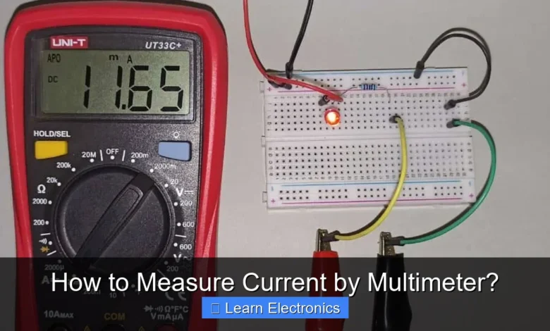
Practical Example: Measuring Current in a Simple Circuit
Let’s say you have a simple circuit with a 9V battery, a switch, an LED, and a current-limiting resistor. To measure the current flowing through the LED:
- Turn off the 9V battery.
- Disconnect one lead of the LED from the circuit.
- Set your multimeter to the ‘mA DC’ range (e.g., 200mA) and ensure the red probe is in the ‘mA’ jack and the black probe is in ‘COM’.
- Connect the red probe to the circuit point that was previously connected to the LED’s positive lead.
- Connect the black probe to the positive lead of the LED.
- Turn on the 9V battery. The LED should light up, and your multimeter will display the current flowing through it.
Reading and Interpreting Current Measurements
Once you have a reading, understanding what the numbers mean is the next step.
Understanding Units (Amps, Milliamps, Microamps)
The unit displayed on your multimeter will correspond to the range you selected. Pay close attention to whether the reading is in Amps (A), Milliamps (mA), or Microamps (µA). For example, a reading of “150” on the 200mA range means 150 milliamperes (0.15 Amps).
Dealing with Negative Readings
A negative reading (e.g., -0.15A) simply indicates that the current is flowing in the opposite direction from what you expected or how you connected your probes. It doesn’t mean anything is wrong with the current magnitude itself; it’s just a directional indicator. If you prefer a positive reading, simply reverse the multimeter’s probe connections in the circuit.
Common Current Ranges
Here’s a general guide to common current ranges and their applications:
| Current Range | Typical Application | Multimeter Port/Setting |
|---|---|---|
| Microamps (µA) | Leakage current, quiescent current of low-power devices, sensor outputs | µA port, µA setting |
| Milliamps (mA) | LED circuits, microcontroller current, small motors, many common electronic circuits | mA port, mA setting |
| Amps (A) | Power supplies, car batteries, appliance current draw, larger motors | 10A/20A port, A setting |
Common Pitfalls and Troubleshooting Tips
Even with careful preparation, issues can arise. Knowing how to troubleshoot can save time and prevent further damage.
Blown Fuse
If your multimeter displays “OL” (Overload) or “0.00” when you expect current to flow, and you’ve confirmed the circuit is operational, a blown fuse in your multimeter is the most likely culprit. Replace the fuse with one of the correct type and rating. Always keep spare fuses on hand.
Incorrect Circuit Break
Ensure you’ve genuinely broken the circuit and inserted the multimeter in series. If there’s an alternative path for the current (a parallel path around your multimeter), you won’t get an accurate reading, or any reading at all. Double-check your connections.
Auto-ranging vs. Manual-ranging Issues
For auto-ranging multimeters, ensure you’ve selected the correct AC or DC current type. For manual-ranging meters, confirm you’ve started with the highest range and progressively lowered it until a stable reading appears. An “OL” on a manual-ranging meter might simply mean the current is higher than the selected range.
Tips for Accurate Current Measurement by Multimeter
- Minimize Resistance: Ensure your multimeter leads are in good condition and making solid contact. Poor connections can introduce resistance and affect readings.
- Isolate the Component: If you need to measure current through a specific component, try to isolate it or ensure the circuit path through your multimeter is exclusive to that component.
- Account for AC vs. DC: Always select the appropriate AC or DC current setting. Measuring DC current on an AC setting (or vice versa) will result in inaccurate or zero readings.
- Avoid Transient Spikes: Some circuits, especially those with motors or inductive loads, can have current spikes at startup. Be aware of these and consider using multimeters with “Min/Max” functions if observing such behavior.
- Practice: The more you practice this method, the more intuitive it becomes. Start with simple circuits to build confidence.
Conclusion
Measuring current with a multimeter is an indispensable skill for anyone delving into electronics. While it requires a specific approach—connecting the meter in series and breaking the circuit—and adherence to safety protocols, the process is straightforward once understood. Always remember to de-energize circuits, select the correct ports and ranges, and prioritize safety to protect both yourself and your equipment. By following the steps outlined, you can accurately diagnose, analyze, and troubleshoot electronic circuits, empowering your learning and project endeavors in electronics.
Frequently Asked Questions
How do I connect a multimeter to measure current?
To measure current, you must connect your multimeter in series with the circuit you want to measure. This means breaking the circuit and inserting the multimeter into the gap so that the current flows through it. Ensure the probes are in the correct current jacks (mA/A and COM) and the rotary switch is set to the appropriate current range.
What safety precautions should I take when measuring current with a multimeter?
Always ensure the circuit’s power is off before connecting the multimeter to prevent accidental shorts or damage. Be mindful of the multimeter’s maximum current rating and choose a range higher than the expected current to avoid blowing its internal fuses. Never measure current in parallel across a voltage source, as this will create a short circuit.
Why is my multimeter showing zero or an incorrect current reading?
If your multimeter shows zero, first check if it’s properly connected in series within the circuit and if the circuit itself is powered. Ensure the probes are firmly inserted into the correct current jacks (mA/A and COM) and the correct measurement range is selected. A blown fuse inside the multimeter is also a common cause for zero readings when attempting to measure current.
Can I measure both AC and DC current with a standard multimeter?
Most standard multimeters can measure both AC (alternating current) and DC (direct current), but it’s crucial to select the correct mode on your device. Look for symbols like “A~” for AC current and “A-” or “A=” for DC current on the rotary dial. Using the wrong mode will result in an inaccurate or no current reading.
As an Amazon Associate, I earn commission from qualifying purchases.


