How to Measure Capacitor in Multimeter? Measuring a capacitor with a multimeter involves selecting the capacitance function, safely discharging the capacitor, and connecting the probes correctly to get a reading of its farad value. This technique is crucial for diagnosing electronic components and ensuring circuit functionality.
Understanding the proper steps for this process helps in identifying faulty components and maintaining the integrity of electronic devices, making it an essential skill for hobbyists and professionals alike.
Quick Answers to Common Questions
My multimeter has a dial with many symbols. How do I know if it can measure capacitors?
Great question! To check if your multimeter can measure a capacitor, look for a dedicated capacitance symbol (often two parallel lines, one curved) or an ‘F’ (for Farads) on its rotary dial. If you see it, your multimeter has the capability to measure capacitor values!
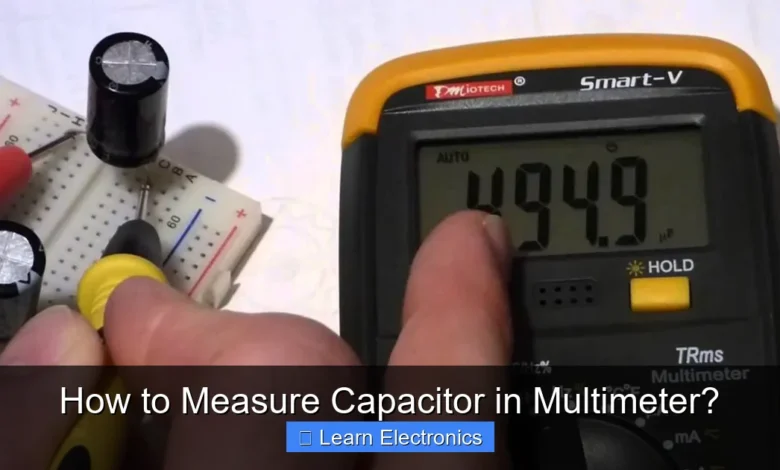
What’s the right setting on my multimeter to measure a capacitor?
Once you’ve confirmed your multimeter has the feature, turn the dial to the capacitance setting, usually marked with ‘F’ (for Farads) or the capacitor symbol. If your multimeter isn’t auto-ranging, start with a higher range and adjust downwards until you get a stable reading for an accurate measure capacitor in multimeter test.
How do I actually connect a capacitor to the multimeter for measurement?
Before connecting, always safely discharge the capacitor first to prevent damage! Then, simply insert the capacitor’s leads into the designated multimeter jacks – typically COM and the jack marked for capacitance or VΩmA – making sure there’s good, firm contact for a reliable measurement.
📑 Table of Contents
- Understanding Capacitors and Multimeters
- Essential Tools and Safety Precautions
- Step-by-Step Guide: How to Measure Capacitor in Multimeter
- Advanced Techniques and Considerations
- Troubleshooting and Advanced Techniques for How to Measure Capacitor in Multimeter
- Practical Tips for Accurate Capacitance Measurement
- Conclusion
Understanding Capacitors and Multimeters
Before diving into the measurement process, it’s vital to have a foundational understanding of what capacitors are and how multimeters function in this context. Capacitors are fundamental electronic components used to store electrical energy in an electric field. They are found in almost every electronic circuit, performing tasks like filtering, smoothing power supplies, timing, and coupling signals.
What is a Capacitor?
A capacitor typically consists of two conductive plates separated by a dielectric (insulating) material. When a voltage is applied across these plates, an electric field forms, and the capacitor stores charge. The unit of capacitance is the Farad (F), though in practical electronics, you’ll most often encounter microfarads (µF), nanofarads (nF), and picofarads (pF). Capacitors come in various types, including electrolytic, ceramic, film, and tantalum, each with specific characteristics and applications.
Types of Multimeters and Capacitance Measurement
Multimeters are versatile tools used to measure various electrical properties like voltage, current, and resistance. When it comes to capacitance, not all multimeters are created equal. Digital multimeters (DMMs) are generally preferred for this task due to their accuracy and ease of reading. Many modern DMMs include a dedicated capacitance measurement function, often indicated by a symbol resembling a capacitor (two parallel lines, one curved). Analog multimeters, while useful for other measurements, typically do not have a capacitance function and are less suitable for accurate capacitor checks.
- Digital Multimeters (DMMs): Offer a dedicated capacitance range, displaying readings directly in farads (µF, nF, pF). They often have auto-ranging capabilities, simplifying the measurement.
- Analog Multimeters: Generally lack a dedicated capacitance function. While some advanced models might allow for indirect checks (e.g., observing needle movement during charging), this is not a precise method for determining capacitance value.
Essential Tools and Safety Precautions
Safety is paramount when working with electronics, especially when dealing with capacitors that can store significant charges. Always prioritize safety before starting any measurement.
Tools You’ll Need
- Digital Multimeter with Capacitance Function: The primary tool for the job. Ensure its batteries are fresh for accurate readings.
- Insulated Test Leads: Standard with most multimeters, but ensure they are in good condition without any frayed wires.
- Discharge Tool (Optional but Recommended): A resistor (e.g., 1kΩ 5W for larger caps, smaller for smaller caps) with insulated leads to safely discharge capacitors. Alternatively, a screwdriver with an insulated handle can be used, but extreme caution is advised for high voltage capacitors.
- Safety Glasses: To protect your eyes from potential arcing or component failure.
- Gloves: Non-conductive gloves can provide an extra layer of protection.
Safety First: Discharging Capacitors
Capacitors, particularly large electrolytic types used in power supplies, can store a lethal charge even after power is removed from a circuit. Always discharge them safely before handling or measuring. Failure to do so can result in severe electric shock or damage to your multimeter.
- Disconnect Power: Ensure the circuit containing the capacitor is completely powered off and unplugged from any power source.
- Locate the Capacitor: Identify the capacitor(s) you intend to measure.
- Discharge Method:
- For small capacitors (e.g., <1µF, <50V): Most small capacitors discharge rapidly when power is removed, but it's still good practice to short their terminals with a resistor.
- For larger capacitors (e.g.,>1µF,>50V): Use a suitable discharge resistor. Connect one lead of the resistor to one capacitor terminal and the other lead to the second terminal. Hold it in place for a few seconds (or longer for very large capacitors) until you confirm the voltage has dropped to zero using your multimeter’s voltage function. A 1kΩ, 5W resistor is a good general-purpose choice.
- Avoid direct shorting with a screwdriver, especially for large capacitors, as this can create a dangerous spark and potentially damage the capacitor or surrounding components.
- Verify Discharge: After discharging, set your multimeter to DC voltage mode and touch the probes across the capacitor terminals. The reading should be close to 0V. If not, continue the discharge process.
Step-by-Step Guide: How to Measure Capacitor in Multimeter
Once safety precautions are observed and your tools are ready, you can proceed with the actual measurement process. This section provides a clear, step-by-step approach to obtaining accurate readings.
Preparing the Capacitor
- Remove from Circuit (Recommended): For the most accurate readings, it’s best to remove the capacitor from the circuit. This prevents other components from interfering with the measurement. Desolder the capacitor if necessary.
- Clean Terminals: Ensure the capacitor’s terminals are clean and free of solder residue or corrosion, which can affect contact and accuracy.
- Discharge (Again, if necessary): Double-check that the capacitor is fully discharged, especially if it has been out of the circuit for a while or if you are unsure of its prior state.
Setting Up Your Multimeter
- Power On: Turn on your digital multimeter.
- Select Capacitance Mode: Rotate the dial to the capacitance function. This is often denoted by a capacitor symbol (two parallel lines, one curved). Some multimeters may share this setting with other functions, requiring you to press a “Shift” or “Function” button to toggle to capacitance mode.
- Insert Test Leads: Connect the black test lead to the “COM” (common) jack and the red test lead to the jack labeled for capacitance measurement (often shared with VΩmA or similar, check your multimeter’s manual).
Taking the Measurement
- Connect Probes: Carefully touch the red test lead to one terminal of the capacitor and the black test lead to the other terminal.
- For Polarized Capacitors (Electrolytic, Tantalum): These capacitors have a positive (+) and negative (-) terminal. Typically, the negative lead is marked with a stripe or a minus sign. Connect the red probe to the positive terminal and the black probe to the negative terminal. While some multimeters may still give a reading if connected in reverse, it’s best practice to connect correctly.
- For Non-Polarized Capacitors (Ceramic, Film): These capacitors have no specific polarity, so the probe connection order does not matter.
- Wait for Reading: The multimeter will start to charge the capacitor and then measure its capacitance. This may take a few seconds, especially for larger capacitors, as the multimeter needs time to cycle through its internal testing process. Wait for the display to stabilize and show a reading.
- Record Reading: Note down the displayed value and its unit (e.g., 47 µF, 100 nF).
Interpreting the Results
Compare the measured value with the capacitor’s nominal value printed on its body. Due to manufacturing tolerances, a reading within +/- 5% to 20% of the labeled value is generally considered acceptable. If the reading is significantly off, or if the multimeter displays “OL” (overload/open circuit) or a very low value for a larger capacitor, it indicates a potential fault.
Advanced Techniques and Considerations
Beyond simple capacitance value measurement, there are other aspects to consider for a comprehensive assessment of a capacitor’s health.
Measuring ESR (Equivalent Series Resistance)
While basic multimeters measure capacitance, they typically don’t measure ESR. ESR is the internal resistance of a capacitor and can increase significantly as a capacitor ages or fails, even if its capacitance value remains relatively stable. High ESR can cause circuit malfunctions, especially in power supplies. Specialized ESR meters are used for this, though some advanced DMMs may include an ESR function. If your multimeter doesn’t have an ESR function, a reading of the capacitance alone might not fully diagnose a faulty capacitor in all cases.
Dealing with Polarized Capacitors
Polarized capacitors, like electrolytics, must be installed with the correct polarity in a circuit. Incorrect installation can lead to damage, overheating, or even explosion. When measuring these components, it’s good practice to observe polarity, although for measuring capacitance value, most modern DMMs are quite forgiving. However, always ensure they are fully discharged before testing.
Troubleshooting Common Issues with Capacitor Measurement
- “OL” or Infinite Reading: If the multimeter displays “OL” (Over Load) or an infinite value for a capacitor that should have a specific capacitance, it usually means the capacitor is open-circuited (internal break) or the contacts are poor.
- Zero or Very Low Reading: A reading of zero or a significantly low value could indicate a short-circuited capacitor (internal short) or a deeply discharged capacitor that the multimeter cannot charge.
- Unstable Readings: Fluctuating or unstable readings might point to a leaky capacitor (where the dielectric material is degrading and allowing current to pass through) or poor probe contact.
- Tolerance Issues: Always remember manufacturing tolerances. A 100µF capacitor measuring 90µF might be perfectly fine if its tolerance is +/- 10%.
Troubleshooting and Advanced Techniques for How to Measure Capacitor in Multimeter
Sometimes, simply measuring the capacitance value isn’t enough to fully diagnose a capacitor, or you might encounter issues during the measurement process. Understanding common problems and alternative checks can enhance your troubleshooting capabilities.
Understanding Tolerance and Nominal Values
Capacitors are manufactured with a specified tolerance, indicating the permissible deviation from their nominal (labeled) value. For example, a 100µF capacitor with a ±10% tolerance should measure between 90µF and 110µF. It’s crucial to consult the component’s datasheet or typical industry standards to know what range is acceptable. Readings outside this range usually signify a faulty component.
| Capacitor Type | Typical Tolerance |
|---|---|
| Electrolytic | ±10% to ±20% |
| Ceramic (General Purpose) | ±5% to ±20% |
| Film | ±1% to ±10% |
| Tantalum | ±10% to ±20% |
Identifying Faulty Capacitors
Beyond incorrect capacitance values, other symptoms can indicate a failing capacitor:
- Physical Damage: Bulging tops (especially on electrolytic capacitors), leaking electrolyte, or discolored heat shrink indicate severe failure.
- Open Circuit: A capacitor that reads “OL” or no value on the multimeter’s capacitance range is open, meaning there’s a break in its internal connection.
- Short Circuit: A capacitor that reads near 0Ω on a resistance range (after full discharge) or causes a low resistance reading across its terminals (if still in circuit) is likely shorted. If shorted, it will also read 0 on a capacitance meter.
- Leaky Capacitor: A leaky capacitor slowly loses its charge. While a DMM’s capacitance function won’t directly show leakage, an indirect method for larger capacitors is to charge it with a DC voltage, then remove the source and monitor the voltage decay over time with the multimeter’s voltage function. A rapidly dropping voltage indicates leakage.
Using a Multimeter for Basic Continuity and Resistance Checks (When Capacitance Function is Absent)
If your multimeter lacks a dedicated capacitance function, you can perform very basic, qualitative checks for larger electrolytic capacitors using the resistance (ohm) range. This method is not for measuring the actual capacitance but for identifying gross failures (shorts or opens).
- Discharge the Capacitor: Crucial for safety and accurate measurement.
- Set Multimeter to Resistance (Ω) Range: Choose a high range (e.g., 10kΩ or 100kΩ).
- Connect Probes: Touch the red probe to the positive terminal and the black probe to the negative terminal (for polarized caps).
- Observe Reading:
- Initially, the multimeter should display a low resistance value, which will gradually increase as the capacitor charges from the multimeter’s internal battery.
- Eventually, the reading should trend towards “OL” or infinite resistance as the capacitor fully charges.
- If the reading immediately goes to “OL” and stays there, the capacitor is likely open.
- If the reading immediately goes to a very low resistance and stays there, the capacitor is likely shorted.
This method is a rough guide and less precise than a dedicated capacitance meter but can help identify completely dead capacitors.
Practical Tips for Accurate Capacitance Measurement
Achieving reliable capacitance readings requires attention to detail and good measurement practices. Follow these tips to ensure accuracy:
- Always Discharge: We cannot stress this enough. Even low-voltage capacitors can hold enough charge to damage sensitive multimeter circuitry or give you a painful shock.
- Isolate the Capacitor: Whenever possible, remove the capacitor from the circuit. In-circuit measurements can be misleading due to parallel components that might influence the reading.
- Clean Connections: Ensure the test probes make solid, clean contact with the capacitor terminals. Dirt, corrosion, or old solder can introduce resistance and skew readings.
- Mind Polarity for Polarized Caps: Connect the red probe to positive and the black probe to negative for electrolytic and tantalum capacitors.
- Wait for Stability: Capacitors, especially larger ones, take time to charge and for the multimeter to process the measurement. Be patient and wait for the reading on the display to stabilize.
- Consider Temperature: Capacitor values can vary slightly with temperature. If critical measurements are needed, ensure the capacitor is at room temperature.
- Use Good Quality Probes: Cheap or damaged probes can have high internal resistance, affecting the accuracy of small capacitance measurements.
- Consult the Manual: Every multimeter is slightly different. Refer to your multimeter’s user manual for specific instructions on how to measure capacitance and any unique features it might have.
Conclusion
Measuring capacitors with a multimeter is an indispensable skill for anyone working with electronics. By following the comprehensive steps outlined, from understanding the basics to implementing advanced techniques, you can accurately assess the health and value of these critical components. Always prioritize safety by properly discharging capacitors before handling them. Mastering this method not only helps in troubleshooting faulty circuits but also contributes significantly to a deeper understanding of electronic components. With practice and adherence to best practices, you’ll gain confidence in your ability to measure and diagnose capacitors effectively.
Frequently Asked Questions
What kind of multimeter do I need to accurately measure a capacitor?
To accurately measure capacitance, you need a digital multimeter (DMM) that includes a dedicated capacitance measurement function. Look for a symbol like a capacitor or “F” (for Farad) on the dial of your multimeter. Basic multimeters typically only measure voltage, current, and resistance.
How should I prepare a capacitor before measuring it with a multimeter?
Before measuring any capacitor, especially larger ones, it’s crucial to discharge it completely to ensure safety and prevent damage to your multimeter. You can do this by carefully shorting its leads with a resistor or a screwdriver across its terminals. Always verify it’s discharged before proceeding.
Can I measure a capacitor if my multimeter does not have a capacitance setting?
Unfortunately, if your multimeter lacks a dedicated capacitance setting, you cannot directly measure its value. While some advanced techniques involving resistance and a stopwatch can estimate capacitance through an R-C time constant, these are not direct measurements and are less precise.
How do I connect a capacitor to my multimeter and interpret the reading?
First, select the appropriate capacitance range on your multimeter, ensuring it’s higher than the capacitor’s expected value. Then, connect the capacitor’s leads to the multimeter’s input jacks (usually marked with “C” or shared with voltage/resistance). The multimeter will display the capacitance value, typically in microfarads (µF), nanofarads (nF), or picofarads (pF).
As an Amazon Associate, I earn commission from qualifying purchases.


