How to Measure an Inductor? is a fundamental skill in electronics, crucial for circuit design, troubleshooting, and ensuring component specifications are met. This process typically involves dedicated equipment to determine an inductor’s precise inductance value and other parasitic characteristics. Understanding this technique is vital for anyone working with electronic circuits.
Quick Answers to Common Questions
What’s the essential tool for accurately measuring an inductor?
The most accurate way to measure an inductor is by using an LCR meter, which is specifically designed to measure Inductance (L), Capacitance (C), and Resistance (R). This specialized equipment gives you precise readings of the inductor’s value.
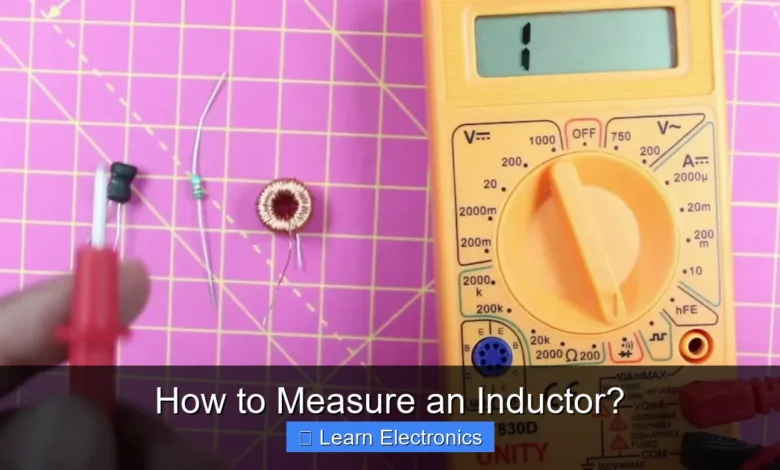
Can I use a standard multimeter to measure an inductor?
Unfortunately, most standard multimeters can’t directly measure inductance, though some higher-end models might have a limited inductance range. For reliable results and to truly measure an inductor, an LCR meter is your best bet.
Why is it important to accurately measure an inductor?
Accurately measuring an inductor is crucial for ensuring your circuit designs work as intended, whether you’re building filters, oscillators, or power converters. It helps verify components, troubleshoot issues, and match specifications for optimal circuit performance.
📑 Table of Contents
Understanding Inductance and Its Importance
An inductor is a passive two-terminal electrical component that stores energy in a magnetic field when electric current flows through it. This property, known as inductance, is measured in Henries (H) and dictates how much voltage is induced across the inductor for a given rate of change of current.
What is an Inductor?
At its core, an inductor is typically a coil of wire, sometimes wrapped around a magnetic core (like ferrite or iron) to enhance its magnetic properties. When current passes through the coil, it generates a magnetic field. Any change in this current causes a change in the magnetic field, which in turn induces a voltage across the inductor itself, opposing the change in current. This principle is fundamental to many electronic applications, from power supplies to filters and oscillators.
Why Accurate Measurement Matters?
Accurate measurement of inductance is paramount for several reasons:
- Circuit Design: Ensuring the correct inductor value is used for filter cutoff frequencies, resonant circuits, and timing applications.
- Quality Control: Verifying that manufactured inductors meet their specified tolerances.
- Troubleshooting: Identifying faulty components in a circuit where an inductor might have drifted in value or become open/shorted.
- Component Matching: Pairing inductors with similar characteristics for balanced or critical applications.
- Understanding Parasitics: Real inductors are not ideal; they possess parasitic resistance (ESR) and capacitance (ESL) that affect their performance at different frequencies. Measuring these can be crucial.
Essential Tools for Inductor Measurement
While a standard multimeter might seem like a go-to tool for electrical measurements, it typically cannot directly measure inductance. Specialized instruments are required to accurately quantify this property.
The LCR Meter: Your Primary Tool
The most common and accurate instrument for measuring inductance is an LCR meter. LCR stands for Inductance (L), Capacitance (C), and Resistance (R), indicating its ability to measure all three passive component values. LCR meters work by applying an AC signal of a known frequency and amplitude to the component under test and then measuring the resulting current and phase shift to calculate inductance. High-end LCR meters can test components at various frequencies, which is crucial for characterizing inductors that behave differently depending on the signal frequency.
Oscilloscope and Function Generator (Indirect Method)
For those without a dedicated LCR meter, an oscilloscope and a function generator can be used for indirect measurement, particularly employing resonance or impedance methods. This approach requires building a test circuit around the inductor and using the instruments to analyze the circuit’s response. While less direct, it provides valuable insight into the inductor’s behavior within a circuit context.
Multimeter Limitations
Most standard digital multimeters (DMMs) only measure resistance, voltage, and current. While some advanced DMMs may include a basic capacitance measurement function, very few offer direct inductance measurement. The reason is that inductance measurement relies on AC characteristics (reactance and phase shift), which are not typically handled by the DC-oriented measurements of a basic DMM. At best, a DMM can verify continuity (very low resistance) to check if an inductor coil is open or shorted, but not its actual inductance value.
Direct Methods: How to Measure an Inductor with an LCR Meter
Measuring inductance directly with an LCR meter is the most straightforward and accurate method. It provides a quick and reliable reading of the component’s value.
Step-by-Step Process
- Power On and Calibrate: Turn on your LCR meter and allow it to warm up as per the manufacturer’s instructions. Perform any necessary open/short calibrations to ensure accuracy.
- Select Measurement Mode: Choose the ‘L’ (Inductance) measurement mode.
- Set Test Frequency: Select an appropriate test frequency. For most general-purpose inductors, 1 kHz or 10 kHz is common. For RF inductors, a higher frequency (e.g., 100 kHz or 1 MHz) might be more relevant to mimic their actual operating conditions.
- Connect the Inductor: Carefully connect the inductor to the LCR meter’s test terminals. For through-hole components, use crocodile clips or dedicated test leads. For surface-mount devices (SMD), specialized tweezers or test fixtures are required. Ensure good contact and minimize lead length to reduce parasitic effects.
- Read the Value: The LCR meter will display the inductance value (L) in Henries (H), millihenries (mH), or microhenries (µH). Many LCR meters also display the equivalent series resistance (ESR) or the quality factor (Q) simultaneously.
- Record and Analyze: Note down the measured value and compare it to the inductor’s nominal value or specified tolerance.
Interpreting Readings
Beyond the inductance value, pay attention to:
- ESR (Equivalent Series Resistance): This represents the real resistance of the inductor’s winding and core losses. A lower ESR generally indicates a higher quality inductor, especially for power applications.
- Q Factor (Quality Factor): Defined as the ratio of an inductor’s inductive reactance to its ESR (Q = XL/ESR). A higher Q factor means the inductor is closer to an ideal component, dissipating less energy as heat.
Considerations for LCR Meter Measurement
The accuracy of your reading can be influenced by:
- Test Frequency: Inductance values can vary with frequency due to parasitic effects and core losses. Always measure at a frequency relevant to your application.
- Measurement Range: Ensure the inductor’s value falls within the meter’s optimal measurement range for best accuracy.
- Temperature: Temperature can affect core materials and wire resistance, subtly changing inductance.
Indirect Measurement Techniques
When an LCR meter isn’t available, or for understanding an inductor’s behavior in a live circuit, indirect methods can be employed. These often involve constructing a simple test circuit and using other common lab equipment.
Resonance Method (Using an RLC Circuit)
This approach involves creating a series or parallel RLC (Resistor-Inductor-Capacitor) circuit. When driven by a variable frequency function generator, the circuit will exhibit resonance at a specific frequency where the inductive reactance (XL) equals the capacitive reactance (XC).
- Build a series RLC circuit with your unknown inductor (L), a known capacitor (C), and a small resistor (R) for current limiting/sensing.
- Apply a sine wave from a function generator across the circuit and monitor the voltage across the resistor with an oscilloscope.
- Vary the function generator’s frequency until the current (indicated by the voltage across R) is maximum. This is the resonant frequency (f0).
- The formula for resonant frequency is f0 = 1 / (2π√LC).
- Rearranging for L, you get L = 1 / (4π²f0²C). Plug in your measured f0 and known C to calculate L.
Impedance Method (AC Voltage/Current)
This method requires a function generator, an oscilloscope, and a known resistor. The inductor’s impedance can be calculated from the voltage and current measurements.
- Connect the inductor in series with a known resistor (R) to a function generator.
- Measure the voltage across the series combination (Vtotal) and the voltage across the resistor (VR) using the oscilloscope.
- The current (I) through the circuit is VR / R.
- The inductive reactance (XL) can be found using the formula for impedance of an RL series circuit: Z = √(R² + XL²). Since Z = Vtotal / I, you can solve for XL.
- Once XL is known, use the formula XL = 2πfL to calculate L, where f is the test frequency from the function generator.
Inductor Test Circuits (Simple DIY Approaches)
Various simple test circuits can be designed to provide an approximate measure. One common method involves using the inductor in a timer circuit, like a 555 timer configured as an astable multivibrator. The frequency of oscillation can be influenced by the inductor and a known capacitor/resistor, allowing for calculation of the inductance. These methods are typically less precise but can be useful for quick checks or educational purposes.
Factors Affecting Inductor Measurements
The characteristics of an inductor are not always static. Several factors can influence its measured value, especially in real-world applications.
Test Frequency
As mentioned, the frequency at which an inductor is measured significantly impacts its apparent inductance. At very high frequencies, parasitic capacitance can cause the inductor to resonate, and beyond its self-resonant frequency (SRF), it might even behave capacitively. Core losses also increase with frequency, affecting the Q factor and effective inductance.
Parasitic Capacitance and Resistance
- Parasitic Capacitance (Cp): Every coil has some inherent capacitance between its turns, known as parasitic capacitance. At higher frequencies, this capacitance becomes significant and can cause the inductor to resonate or act like a capacitor.
- Parasitic Resistance (ESR): The wire used to wind the coil has resistance, and the magnetic core material also contributes to losses. This ESR reduces the Q factor and efficiency of the inductor.
Core Material and Saturation
Inductors with magnetic cores (like ferrite) have significantly higher inductance for a given number of turns compared to air-core inductors. However, magnetic cores can saturate if the current flowing through the inductor is too high. When saturated, the core can no longer support an increase in the magnetic field, and the inductance drops sharply. This is a crucial consideration for power inductors.
Temperature Effects
The resistivity of the wire windings changes with temperature. This directly affects the ESR. Core materials can also exhibit changes in permeability with temperature, leading to slight variations in inductance.
Practical Tips for Accurately Measuring an Inductor
Achieving precise and reliable inductor measurements requires careful attention to detail and proper technique.
Calibration and Setup
Always calibrate your LCR meter before starting measurements, especially when switching test frequencies or using different test fixtures. Ensure proper contact with the component and keep test leads as short as possible to minimize their own parasitic inductance and capacitance.
Lead Length and Proximity Effects
Long test leads can introduce their own parasitic inductance and capacitance, skewing measurements, especially for small inductance values. Use the shortest possible leads or dedicated test fixtures. Be mindful of placing inductors too close to other metallic objects or components during measurement, as this can affect the magnetic field and thus the measured inductance.
Multiple Measurements and Averaging
For critical applications, take several measurements and average the results, especially if you notice minor fluctuations. This helps to mitigate random errors and provides a more robust estimate of the true inductance.
Understanding Inductor Tolerances
Most inductors come with a specified tolerance (e.g., ±5%, ±10%, ±20%). When you measure an inductor, ensure your reading falls within this tolerance range of its nominal value. If it’s outside, the component might be faulty or unsuitable for your application.
Common Inductor Measurement Ranges and Typical Values
The table below provides a general guide for common inductor types and their typical inductance ranges. While LCR meters are versatile, knowing the approximate range helps in selecting the correct measurement setup.
| Inductor Type | Typical Inductance Range | Common Application | Typical Test Frequency (LCR Meter) |
|---|---|---|---|
| Small SMD Inductors | 1 nH – 100 µH | RF circuits, filters | 100 kHz – 1 MHz |
| Power Inductors (Chokes) | 1 µH – 10 mH | DC-DC converters, power supplies | 1 kHz – 10 kHz |
| Audio Frequency Inductors | 1 mH – 1 H | Audio filters, crossovers | 100 Hz – 1 kHz |
| Large Chokes (Mains Filter) | 1 H – 100 H | Power line filtering | 50 Hz – 120 Hz |
| Ferrite Beads | Impedance specified (not L) | EMI suppression | 10 MHz – 1 GHz |
Note that ferrite beads are often characterized by their impedance at a specific frequency rather than a strict inductance value, as their behavior is highly frequency-dependent.
Accurately measuring an inductor is an indispensable skill in electronics, critical for successful circuit design, diagnosis, and quality assurance. While an LCR meter offers the most precise and direct method, understanding indirect techniques using an oscilloscope and function generator can provide valuable insights and practical alternatives. By paying close attention to factors like test frequency, parasitic effects, and proper measurement practices, you can confidently determine the characteristics of inductors and ensure their optimal performance in your electronic projects. Embrace these techniques to enhance your electronics expertise and achieve more reliable results.
Frequently Asked Questions
What is the primary property I’m trying to measure when I measure an inductor?
When measuring an inductor, your primary goal is typically to determine its inductance value, expressed in Henrys (H). This value quantifies the inductor’s ability to store energy in a magnetic field and oppose changes in current. You might also measure its DC resistance (DCR) and quality factor (Q).
What equipment is typically used to measure an inductor accurately?
The most common and accurate tool for measuring an inductor is an LCR meter. This specialized device can directly measure inductance (L), capacitance (C), and resistance (R) at various frequencies. For less critical applications, some advanced multimeters with an inductance function can provide an estimate.
Can I measure an inductor with a standard multimeter?
Most standard multimeters do not have a built-in function to measure inductance directly. While some advanced models include this feature, basic multimeters can only measure resistance, voltage, and current. You can, however, use a multimeter to measure the DC resistance (DCR) of an inductor’s winding, which can indicate its health but not its actual inductance value.
How do I measure an inductor when it’s already in a circuit?
Measuring an inductor accurately while it’s in-circuit is challenging because other components can influence the reading. It is generally recommended to desolder at least one leg of the inductor from the circuit before measuring it with an LCR meter. If desoldering isn’t feasible, specialized in-circuit testers or techniques might be required, but results can be less accurate.
What factors can affect the accuracy when measuring an inductor?
Several factors can influence the accuracy of an inductor measurement, including the test frequency, temperature, and parasitic elements. The quality of the test leads and any stray capacitance or inductance in the measurement setup can also introduce errors. Ensure proper calibration and use appropriate test frequencies, especially for high-frequency inductors.
As an Amazon Associate, I earn commission from qualifying purchases.


