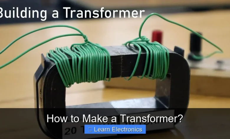
How to Make a Transformer? involves carefully coiling wires around a magnetic core to efficiently step up or step down alternating current (AC) voltage. This fundamental electrical component is critical for everything from power transmission grids to small electronic devices, enabling proper voltage levels where needed.
Mastering this technique requires understanding basic electromagnetic principles, selecting appropriate materials, and meticulous assembly. This guide will walk you through the entire process, empowering you to construct your own functional transformer for educational or hobbyist projects.
Quick Answers to Common Questions
What are the fundamental parts needed to build a transformer?
When learning how to make a transformer, you’ll absolutely need a magnetic core (often laminated iron or ferrite), two distinct coils of insulated copper wire for your primary and secondary windings, and suitable insulating materials. These are the core elements for your project!
Is it safe for a beginner to attempt to make a transformer at home?
While the conceptual steps of how to make a transformer are straightforward, working with electricity always demands caution. Start with low-voltage designs and prioritize safety by understanding circuits and insulation thoroughly before you begin your build.
How does a homemade transformer actually change the voltage?
The magic happens through electromagnetic induction! As AC current flows through your primary coil, it generates a changing magnetic field within the core, which then induces a new voltage in the secondary coil, allowing you to step voltage up or down.
📑 Table of Contents
- Understanding the Basics of Transformer Operation
- Essential Components and Tools for Building a Transformer
- Core Selection and Preparation
- Winding the Coils: Primary and Secondary
- Assembly, Insulation, and Testing
- Safety and Practical Considerations
- Common Transformer Specifications and Examples
- Conclusion
Understanding the Basics of Transformer Operation
Before you embark on the practical steps of constructing a transformer, it’s essential to grasp the underlying principles. Transformers operate on the principle of electromagnetic induction, specifically mutual induction. When an alternating current flows through a coil (the primary winding), it creates a continuously changing magnetic field. This fluctuating magnetic field then links with a second coil (the secondary winding), inducing an electromotive force (EMF), or voltage, across its terminals.
Key Concepts
- Primary Winding: The coil connected to the input AC voltage source.
- Secondary Winding: The coil from which the output voltage is drawn.
- Magnetic Core: A material, typically made of laminated iron or ferrite, that provides a low-reluctance path for the magnetic flux, efficiently coupling the primary and secondary windings.
- Turns Ratio: The ratio of the number of turns in the secondary winding to the number of turns in the primary winding (Ns/Np). This ratio directly determines the voltage transformation (Vs/Vp = Ns/Np).
- Step-Up Transformer: Has more turns in the secondary winding than the primary, increasing the output voltage.
- Step-Down Transformer: Has fewer turns in the secondary winding than the primary, decreasing the output voltage.
The core material is crucial. Laminated iron cores are used for power transformers operating at mains frequencies (50/60 Hz) because the laminations help reduce eddy current losses. Ferrite cores are preferred for high-frequency applications, such as in switch-mode power supplies, due to their lower losses at higher frequencies.
Essential Components and Tools for Building a Transformer
To successfully complete the project, you’ll need to gather specific materials and tools. Careful selection of each component is vital for the transformer’s performance and safety. Here’s what you’ll typically require when considering how to make a transformer:
Materials Checklist
- Magnetic Core:
- Laminated Iron Core: For power transformers, choose E-I laminations made of silicon steel. The size and stacking factor will depend on the desired power rating.
- Ferrite Core: For high-frequency applications, select a suitable ferrite core geometry (e.g., E, UI, Pot core).
- Magnet Wire (Enamelled Copper Wire):
- Primary and secondary windings will require insulated copper wire. The gauge (AWG or SWG) depends on the current rating and desired turns. Thicker wire for higher current, thinner for lower.
- Ensure the insulation (enamel) is intact and rated for the expected voltage.
- Insulation Materials:
- Transformer Paper (Nomex, fish paper): For layer-to-layer and winding-to-core insulation.
- Insulation Tape: High-temperature, high-dielectric strength tape (e.g., Kapton tape, Mylar tape).
- Varnish (Optional): Electrical insulating varnish to seal and protect windings.
- Output Terminals/Leads: Heavier gauge insulated wire for connecting to input/output circuits.
- Bobbin (Optional but Recommended): A pre-formed plastic bobbin designed to fit your core helps immensely with winding neat coils.
Tools You’ll Need
- Wire Strippers: For removing enamel from magnet wire ends and insulation from lead wires.
- Soldering Iron and Solder: For connecting winding ends to lead wires.
- Multimeter: Essential for checking resistance, continuity, and later, voltage.
- Vernier Caliper/Micrometer: For precise measurement of wire diameter.
- Gloves and Safety Glasses: Always prioritize safety.
- Coil Winding Machine (Optional): Manual or automatic, simplifies the winding process significantly for larger projects or higher turns counts. For small projects, hand-winding is feasible.
- Vise/Clamps: To hold the core or bobbin securely during winding.
Core Selection and Preparation
The core is the heart of your transformer, guiding the magnetic flux. Its material and construction directly impact efficiency and size. For general purpose mains-frequency transformers, a laminated iron core is the standard choice.
Choosing the Right Core
- Power Rating: The physical size of the core (cross-sectional area) dictates the maximum power it can handle without saturating. Larger cores can handle more power.
- Lamination Type: E-I laminations are common. The ‘E’ sections are interleaved with ‘I’ sections to form a closed magnetic path. This interleaving is crucial for reducing air gaps and preventing core saturation.
- Material Quality: Silicon steel laminations are preferred due to their low hysteresis and eddy current losses.
Preparing the Core
If using E-I laminations:
- Cleanliness: Ensure the laminations are clean and free from rust or burrs.
- Bobbin Fitting: If you have a bobbin, the E-sections of the core will slide into the central opening of the bobbin after the coils are wound.
- Insulation: For safety, consider insulating the central limb of the E-core with a layer of transformer paper or Mylar tape before winding, especially if you are not using a bobbin. This prevents the wire from directly touching the conductive core.
Winding the Coils: Primary and Secondary
This is arguably the most critical and meticulous part of the entire process. Precision in winding ensures optimal performance and safety. The number of turns for each coil is determined by the desired voltage ratio and the core’s characteristics.
Calculating Turns Ratio
First, determine the turns per volt (TPV) for your chosen core and operating frequency. This is often an empirical value or derived from core data sheets. As a rough estimate for mains frequency iron cores, it can be calculated using the formula: TPV = 1 / (4.44 * A * B * f), where A is the core’s cross-sectional area (m²), B is the maximum flux density (typically around 1-1.5 Tesla for silicon steel), and f is the frequency (Hz).
Once you have TPV:
- Primary Turns (Np) = Input Voltage (Vp) × TPV
- Secondary Turns (Ns) = Output Voltage (Vs) × TPV
You’ll also need to calculate the wire gauge based on the current each winding will carry. A good rule of thumb for hobby projects is 2.5-3.5 Amps per square millimeter of wire cross-section.
Winding Procedure
- Prepare the Bobbin/Core: If using a bobbin, secure it firmly. If winding directly on the core, insulate the central limb.
- Start Primary Winding:
- Leave a few inches of wire for the start lead, secure it, and begin winding the primary coil.
- Wind layers neatly and tightly, side-by-side, avoiding crossovers. This minimizes air gaps and ensures efficient coupling.
- At the end of each layer, add a layer of transformer paper or insulation tape for dielectric strength. This prevents short circuits between layers.
- Continue winding layers, adding insulation after each, until the calculated number of primary turns is reached.
- Leave a few inches for the end lead of the primary, and secure it.
- Insulate Between Windings: After completing the primary, apply a substantial layer of insulation (several layers of tape or thick transformer paper) over the entire primary winding. This is crucial for isolating the primary from the secondary, especially when dealing with high voltages.
- Start Secondary Winding:
- Repeat the winding process for the secondary coil, again starting with a lead, winding neatly layer-by-layer, and insulating between layers.
- Wind until the calculated number of secondary turns is reached.
- Leave a few inches for the end lead of the secondary.
Tip: Keep track of your turns! A simple mechanical counter on a winding machine or even manual tally marks can help prevent errors.
Assembly, Insulation, and Testing
With the coils wound, the next steps involve assembling the core, providing final insulation, and thoroughly testing your homemade transformer.
Core Assembly
- Insert E-Laminations: Carefully slide the E-sections of the core into the bobbin’s central opening, alternating their direction (e.g., E facing right, then E facing left, then E facing right). This interleaving technique minimizes air gaps and reduces hum.
- Insert I-Laminations: Once all E-sections are in place, insert the straight I-sections to complete the magnetic circuit.
- Clamp and Secure: Gently press the laminations together. For commercial transformers, the core is often clamped or riveted to prevent vibration and ensure a tight fit. For hobby projects, you might use epoxy or appropriate banding.
Final Insulation and Protection
- Outer Insulation: Wrap the entire coil assembly with a final layer of insulation tape to protect the windings from physical damage and provide additional electrical isolation.
- Varnishing (Optional): Immersing the wound core in electrical insulating varnish and then baking it helps to seal the windings, prevent moisture ingress, improve dielectric strength, and reduce coil vibration (hum).
- Connect Leads: Strip the enamel from the ends of your primary and secondary winding leads (typically about 0.5 inches). Solder these to heavier gauge, flexible insulated wires that will serve as your input and output connections. Ensure these connections are robust and well-insulated with heat shrink tubing or electrical tape.
Initial Testing Steps
Before connecting to mains power, perform these critical checks:
- Continuity Check: Use a multimeter in resistance mode to check for continuity on the primary and secondary windings. There should be a low resistance value (a few ohms to hundreds of ohms, depending on wire length and gauge). An open circuit indicates a break in the winding.
- Insulation Resistance Check (Optional, but Recommended): Use a megohmmeter (insulation tester) to check the resistance between:
- Primary winding and core
- Secondary winding and core
- Primary winding and secondary winding
Ideally, these should show very high resistance (Megaohms), indicating good isolation.
- No-Load Voltage Test:
- Extreme Caution: Connect the primary winding to your intended AC input voltage (e.g., 120V or 240V AC mains) through a current-limiting device or a variac if available.
- Using a multimeter set to AC voltage, measure the output voltage across the secondary winding.
- Compare this measured voltage to your calculated output voltage. Minor deviations are expected, but large discrepancies suggest winding errors or an unsuitable core.
- Load Test (Optional): Once the no-load test is successful, connect a suitable load (resistor or appliance) to the secondary and measure the output voltage under load. Observe if the transformer gets excessively hot.
Safety and Practical Considerations
Working with electricity, especially AC mains voltage, carries significant risks. Safety should always be your paramount concern when you make a transformer.
Crucial Safety Guidelines
- Never Work on Live Circuits: Always disconnect power before touching any part of the transformer or its connections.
- Insulation is Key: Ensure all exposed conductors are properly insulated. Use high-quality electrical tape or heat shrink tubing.
- Grounding: For power transformers, ensuring the core is properly grounded can add a layer of safety against insulation breakdown.
- Fusing: Include fuses on both the primary and secondary sides of your transformer to protect against overcurrent conditions and short circuits.
- Proper Ventilation: Transformers generate heat. Ensure your finished assembly has adequate ventilation, especially if it’s enclosed.
- Seek Expert Advice: If you are unsure about any step, consult with an experienced electrician or electronics hobbyist.
Performance Optimization Tips
- Neat Winding: Tighter, neater windings result in better coupling and less leakage inductance, improving efficiency.
- Layer Insulation: Don’t skimp on insulation between layers and especially between the primary and secondary. This prevents internal shorts and ensures safety.
- Core Material: Use the appropriate core material for your operating frequency.
- Wire Gauge: Choose the correct wire gauge to handle the expected current without excessive resistive losses or overheating.
- Varnishing: While optional for simple projects, varnishing significantly enhances the longevity and reliability of the transformer.
Common Transformer Specifications and Examples
Understanding typical transformer specifications can help you design and build a more effective component. Here’s a brief table illustrating common voltage and current ratings for various applications.
| Application | Primary Voltage (AC) | Secondary Voltage (AC) | Typical Power (VA) | Core Type |
|---|---|---|---|---|
| Small Power Supply | 120V / 240V | 6V, 9V, 12V | 5 – 50 VA | Laminated E-I |
| Audio Amplifier | 120V / 240V | 24V-0-24V, 35V-0-35V | 50 – 500 VA | Laminated E-I / Toroidal |
| Doorbell / HVAC | 120V / 240V | 16V, 24V | 10 – 40 VA | Laminated E-I |
| SMPS (High Freq.) | Variable (DC or rectified AC) | Variable (DC via rectifier) | 10W – 1000W+ | Ferrite Core |
| Isolation Transformer | 120V / 240V | 120V / 240V | 100 – 1000 VA+ | Laminated E-I |
Note: VA (Volt-Ampere) is a measure of apparent power, typically used for transformers to denote their capacity. It is roughly equivalent to Watts for purely resistive loads.
For instance, if you want to power a small 12V DC circuit from a 240V AC mains supply, you would design a step-down transformer with a 240V primary and a 12V secondary. If your calculated TPV is 0.5 turns/volt, your primary would need 120 turns (240V * 0.5 TPV) and your secondary would need 6 turns (12V * 0.5 TPV). The wire gauge for the primary would be chosen for the low primary current, while the secondary wire would be thicker to handle the higher output current.
Conclusion
Successfully constructing a transformer is a rewarding experience that deepens your understanding of fundamental electrical engineering principles. While the process demands precision, patience, and a strong adherence to safety protocols, the ability to tailor a voltage conversion device to your specific needs is incredibly valuable. By carefully selecting your core, calculating winding turns, and meticulously insulating each layer, you can create a functional and reliable component.
Remember, this approach to creating transformers is an excellent learning exercise. For critical or high-power applications, purchasing commercially manufactured transformers is often the safer and more reliable choice due to stringent manufacturing standards and quality control. However, for educational purposes and hobby projects, mastering the practice of making a transformer offers invaluable insights into the world of electronics.
Frequently Asked Questions
What is a transformer and why would I want to make one?
A transformer is an electrical device that transfers electrical energy between two or more circuits through electromagnetic induction, usually for changing voltage levels. Making a transformer can be a valuable educational project to understand electromagnetic principles or for specific low-power applications like small power supplies or isolation.
What essential materials and components are needed to make a transformer?
To construct a basic transformer, you’ll need an iron core (laminated silicon steel or ferrite), insulated copper wire for primary and secondary windings, insulating material (like transformer paper or varnish), and bobbins or forms to wind the coils. Other components may include terminal blocks and a suitable enclosure.
What are the fundamental steps involved in making a transformer?
The basic steps include selecting and preparing your core, winding the primary coil with the calculated number of turns, insulating it, then winding the secondary coil. After winding, secure the coils, ensure proper insulation, and assemble the core sections.
How do I determine the correct wire gauge and number of turns for my transformer windings?
The number of turns is calculated based on the desired voltage ratio and the core’s characteristics, typically using a volts-per-turn constant for your specific core material. Wire gauge is selected based on the current it needs to carry, ensuring it can handle the load without excessive heating.
What safety precautions are crucial when making and testing a homemade transformer?
Always wear appropriate personal protective equipment like safety glasses and insulated gloves. Work with low voltages during initial testing, use proper insulation between windings, and ensure all connections are secure to prevent shorts or shocks. High voltages can be lethal, so extreme caution is paramount.
Can I make a high-voltage power transformer safely at home, and what are the limitations?
While theoretically possible, making a high-voltage power transformer for significant power transfer at home is generally not recommended due to significant safety risks and the complexity of achieving reliable insulation and cooling. Homemade transformers are better suited for low-voltage, low-power, or educational demonstration purposes.
As an Amazon Associate, I earn commission from qualifying purchases.


