How to Check a Capacitor? The process typically involves a combination of visual inspection and electrical measurements to determine its health and functionality. Mastering this technique is crucial for diagnosing and repairing electronic circuits, ensuring optimal performance and longevity.
Understanding the proper methods for assessing these vital components can prevent costly replacements and unnecessary troubleshooting. This approach allows electronics enthusiasts and professionals alike to efficiently identify faulty capacitors, a common cause of circuit malfunctions.
Quick Answers to Common Questions
How can I tell if a capacitor is bad just by looking at it?
Often, a faulty capacitor will show visible signs like bulging at the top or bottom, leakage (a brown crusty residue), or even a popped vent. If you spot any of these, it’s a strong indicator that you need to check a capacitor further or replace it.
What’s the best tool to check a capacitor accurately?
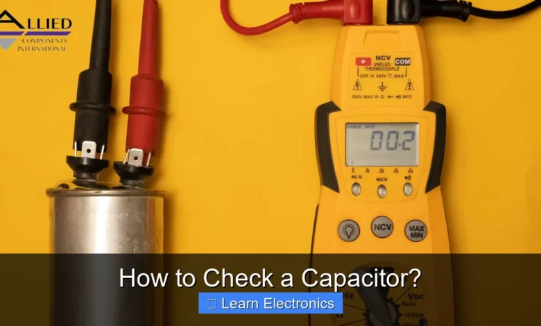
The most common and effective tool to check a capacitor is a multimeter with a capacitance testing function. This allows you to get a precise numerical reading of its actual capacitance.
What should my multimeter tell me when I check a capacitor?
When using a multimeter to check a capacitor, you’re ideally looking for a capacitance reading that’s very close to the value printed on the capacitor itself. A significantly lower reading, zero, or “OL” (overload) usually indicates the capacitor is faulty.
📑 Table of Contents
- Why Is It Important to Test Capacitors?
- Safety First: Precautions Before Any Capacitor Check
- Visual Inspection: The First Step in Checking a Capacitor
- How to Check a Capacitor with a Multimeter
- Advanced Testing: LCR and ESR Meters for Comprehensive Capacitor Analysis
- Practical Considerations and Troubleshooting When Checking Capacitors
Why Is It Important to Test Capacitors?
Capacitors are fundamental components in nearly every electronic circuit, playing crucial roles in energy storage, filtering, timing, and power supply regulation. Over time, due to factors like heat, age, voltage stress, and ripple current, capacitors can degrade. A failing capacitor can lead to a wide array of circuit problems, from intermittent operation and reduced performance to complete device failure. Common symptoms of capacitor failure include flickering displays, buzzing sounds, unstable power, and devices failing to power on.
Regular or diagnostic testing allows you to preemptively identify these issues before they cause significant damage to the circuit or other components. This proactive maintenance can extend the life of your electronic devices and save you from more complex repairs down the line.
Safety First: Precautions Before Any Capacitor Check
Before attempting to check any capacitor, especially large electrolytic types found in power supplies, safety must be your absolute top priority. Capacitors can store significant electrical charge even after a device has been powered off, posing a serious shock hazard. Always follow these essential precautions:
- Disconnect Power: Ensure the device is completely unplugged from its power source and any batteries are removed.
- Discharge the Capacitor: Use a suitable discharge tool or a resistor (e.g., 1k-10k Ohm, 5W) with insulated leads to safely discharge the capacitor. Connect the resistor across the capacitor’s terminals for several seconds. For larger capacitors, verify with a multimeter that the voltage across the terminals has dropped to near zero before proceeding. Never short the terminals directly with a screwdriver or wire, as this can create a dangerous spark and damage the capacitor or circuit.
- Wear Safety Gear: Always wear safety glasses to protect your eyes from potential sparks or chemical leaks. Insulated gloves are also advisable.
- Identify Polarity: Be aware of the polarity of electrolytic capacitors (marked with a stripe or negative sign on one side). Reversing polarity during testing or reinstallation can cause them to fail explosively.
Visual Inspection: The First Step in Checking a Capacitor
Often, the easiest and quickest way to assess a capacitor’s health is through a thorough visual inspection. While not conclusive for all failures, many common capacitor problems are visible to the naked eye. Look for the following signs:
- Bulging Top: Electrolytic capacitors, especially, can develop a bulging or domed top. This indicates that internal pressure from electrolyte gases has built up, often due to overheating or overvoltage, and the capacitor is failing.
- Leaking Electrolyte: Brownish or crusty residue, often resembling dried glue, around the base or vent of an electrolytic capacitor is a clear sign of electrolyte leakage. This fluid is corrosive and can damage the circuit board.
- Swollen Body: Similar to a bulging top, a capacitor that appears generally swollen or distended along its sides is likely failing.
- Physical Damage: Look for any signs of physical damage such as cracks, burns, scorch marks, or damaged leads. These can indicate overheating, overcurrent, or mechanical stress.
- Discolored PCB: Sometimes, the circuit board around a capacitor may appear discolored or burnt, suggesting the capacitor has been operating at excessive temperatures.
If you observe any of these visual cues, the capacitor is almost certainly bad and should be replaced, regardless of any electrical test results.
How to Check a Capacitor with a Multimeter
A standard digital multimeter (DMM) or analog multimeter can perform several basic checks on a capacitor, offering more insight than a visual inspection alone. While not as comprehensive as a dedicated LCR or ESR meter, this method can often identify major faults.
Continuity Test for Shorts
A shorted capacitor will allow current to flow freely through it, which is not its intended function (except momentarily during charging). A multimeter’s continuity function can help detect this:
- Ensure the capacitor is fully discharged.
- Set your multimeter to the continuity or diode test mode.
- Touch the multimeter probes to the capacitor’s terminals.
- If the multimeter beeps continuously or shows a very low resistance (near zero), the capacitor is likely shorted internally and is bad. A good capacitor should not show continuity after initial charging, or only briefly if it’s large enough to charge significantly from the meter’s internal battery.
Resistance Test (Charging Behavior)
This test utilizes the capacitor’s ability to charge and discharge, which can be observed as a change in resistance on an analog multimeter or a fluctuating reading on a digital one.
Using an Analog Multimeter:
- Ensure the capacitor is fully discharged.
- Set the multimeter to a high resistance range (e.g., 1kΩ or 10kΩ).
- Connect the probes to the capacitor terminals, observing polarity for electrolytic types (red to positive, black to negative).
- The needle should quickly deflect towards zero (indicating low resistance as it charges) and then slowly move back towards infinity (high resistance) as the capacitor charges.
- If the needle doesn’t move at all, the capacitor is likely open (a break in the circuit). If it stays near zero, it’s likely shorted. If it deflects but doesn’t return to infinity, it might be leaky.
Using a Digital Multimeter (with capacitance mode):
Many modern DMMs include a capacitance measurement function (often denoted by ‘nF’, ‘µF’, or ‘pF’). This is the most direct way to check a capacitor’s value with a multimeter.
- Ensure the capacitor is fully discharged.
- Remove the capacitor from the circuit to ensure accurate readings.
- Set your DMM to the capacitance measurement mode.
- Connect the probes to the capacitor’s terminals (observing polarity for electrolytic capacitors).
- The display will show the capacitance value. Compare this reading to the value printed on the capacitor. A deviation of more than 10-20% from the nominal value typically indicates a failing capacitor.
- If the meter displays “OL” (over limit) or a very low value for a larger capacitor, it might be open-circuited.
Note: Some lower-end DMMs may not have a capacitance mode, or their range might be limited to smaller capacitance values.
Advanced Testing: LCR and ESR Meters for Comprehensive Capacitor Analysis
For a truly comprehensive assessment, especially for electrolytic capacitors, dedicated LCR (Inductance, Capacitance, Resistance) and ESR (Equivalent Series Resistance) meters are indispensable tools.
Measuring Capacitance
While some DMMs can measure capacitance, a dedicated LCR meter offers higher accuracy and often a wider range. This is especially useful for non-electrolytic capacitors (ceramic, film) where visual inspection or basic multimeter tests might not reveal subtle changes in capacitance.
- Discharge the capacitor and remove it from the circuit.
- Connect the LCR meter probes to the capacitor terminals.
- Select the capacitance measurement mode on the meter.
- Read the value and compare it to the capacitor’s rated value. Significant deviation indicates degradation.
Measuring ESR (Equivalent Series Resistance)
ESR is a critical parameter for electrolytic capacitors, especially in switching power supplies and audio circuits. It represents the internal resistance of the capacitor and tends to increase as the capacitor ages or degrades. A high ESR can severely impact circuit performance, causing issues like excessive heat, ripple voltage, and instability, even if the capacitance value still appears good.
- An ESR meter can often test capacitors in-circuit, which is a significant advantage, but for the most accurate results, remove the capacitor.
- Discharge the capacitor.
- Connect the ESR meter probes to the capacitor terminals.
- Read the ESR value and compare it to known good values for that type and size of capacitor.
Here’s a simplified table of typical ESR values (guideline only, actual values vary significantly by manufacturer, voltage, and series):
| Capacitance (µF) | Voltage (V) | Typical Good ESR (Ohms) | Indication of Failure (Ohms) |
|---|---|---|---|
| 1 – 10 | 50 – 450 | 0.5 – 5.0 | > 10.0 |
| 10 – 100 | 16 – 250 | 0.1 – 2.0 | > 5.0 |
| 100 – 1000 | 10 – 100 | 0.05 – 0.5 | > 1.0 |
| 1000 – 4700 | 6.3 – 50 | 0.01 – 0.1 | > 0.5 |
(Note: These are general guidelines. Always consult datasheets for specific capacitor series when possible.)
Leakage Current Test
For certain applications, particularly in vintage equipment or high-voltage circuits, measuring leakage current is important. A dedicated capacitor leakage tester applies a DC voltage across the capacitor and measures the small current that flows through its dielectric. Excessive leakage current indicates a compromised dielectric and a failing capacitor.
Practical Considerations and Troubleshooting When Checking Capacitors
- In-Circuit vs. Out-of-Circuit: While an ESR meter can often test in-circuit, other tests like capacitance and resistance measurements are usually more accurate when the capacitor is desoldered and tested out of the circuit. This eliminates the influence of other parallel components that might skew readings.
- Intermittent Faults: Some capacitor failures are intermittent, especially those related to temperature. A capacitor might test good when cold but fail when hot. In such cases, replacing suspicious capacitors, even if they test borderline, is often the most practical solution.
- Comparing Values: If you’re troubleshooting a circuit with multiple identical capacitors (e.g., in a filter bank), comparing their measured values to each other can help identify the outlier, even without an exact datasheet.
- Replacement Capacitors: When replacing a faulty capacitor, always ensure the new component matches or exceeds the original’s capacitance, voltage rating, and temperature rating. For electrolytic capacitors, low-ESR types are often preferred for modern switching power supplies.
Learning how to check a capacitor effectively is an indispensable skill for anyone involved in electronics repair or design. From simple visual inspections to sophisticated ESR and LCR measurements, a range of techniques can help you diagnose and resolve circuit issues caused by these critical components. By understanding the proper safety procedures and utilizing the right tools, you can confidently identify failing capacitors and restore electronic devices to full functionality.
Frequently Asked Questions
How can I visually check a capacitor for damage?
Focus on physical signs. Look for bulges or swelling on the top or bottom of the capacitor, especially with electrolytic types. Also, check for any leakage of electrolyte fluid, which often appears as a brownish, crusty residue around the capacitor’s base or vents.
How do I check a capacitor using a multimeter?
Set your multimeter to the capacitance testing mode, if available. If not, use the resistance (ohm) setting on a high range. Connect the probes across the capacitor terminals, observing the initial resistance reading (it should rise and then settle) or the capacitance value displayed.
Can I check a capacitor while it’s still in the circuit?
It is generally not recommended to check a capacitor’s capacitance value while it’s still in-circuit, as other components can interfere with the reading. For accurate results, always desolder at least one leg of the capacitor from the circuit board before testing. Ensure the capacitor is fully discharged beforehand.
What are the signs of a bad capacitor beyond visual inspection?
Besides physical damage, a bad capacitor often shows an incorrect capacitance value when tested with a meter, or a high Equivalent Series Resistance (ESR). In a circuit, symptoms like intermittent operation, power supply instability, or complete device failure can point to a faulty capacitor.
As an Amazon Associate, I earn commission from qualifying purchases.


