How can I Test a Capacitor? Testing a capacitor typically involves checking its capacitance value, equivalent series resistance (ESR), and for any signs of shorts or open circuits. This process is crucial for troubleshooting electronic circuits and ensuring component reliability.
Understanding how to properly test a capacitor can save you time and frustration when diagnosing faulty electronics. Various methods and tools are available, ranging from basic multimeter checks to more specialized equipment.
Quick Answers to Common Questions
What’s the easiest way to test a capacitor quickly?
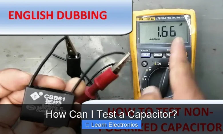
The simplest way to *test a capacitor* is by using a multimeter with a capacitance setting, which will give you a direct reading of its value to compare against what’s printed on the component.
Can I use a regular multimeter to test a capacitor?
Yes, you can use a regular multimeter to *test a capacitor* for basic faults like shorts or open circuits using the resistance (ohms) setting. However, for a precise capacitance value, you’ll need a meter with a dedicated capacitance function.
What are some visual signs a capacitor might be bad even before I test it?
Before you even *test a capacitor*, keep an eye out for visual cues like a bulging top, leaking electrolyte (often a crusty residue), or a discolored/burnt-looking casing. These are strong indicators that the capacitor has failed and needs replacing.
📑 Table of Contents
- Safety First: Essential Precautions Before Testing
- How to Test a Capacitor with Basic Tools (Using a Multimeter)
- Understanding Capacitor Failure Modes and Visual Cues
- Advanced Techniques: How to Test a Capacitor for ESR and Leakage
- Data Table: Quick Reference for Capacitor Health
- Practical Tips for Effective Capacitor Testing and Replacement
Safety First: Essential Precautions Before Testing
Before you begin any capacitor testing, prioritize safety. Capacitors, especially larger ones in power supplies, can store a significant electrical charge even after the power is off, posing a serious shock hazard.
Discharging Capacitors Safely
Always discharge a capacitor before handling or testing it. For smaller capacitors (under 50V), a simple resistor (e.g., 1kΩ to 10kΩ, 1/4W) across its terminals for a few seconds can suffice. For larger, high-voltage capacitors, use a high-wattage resistor (e.g., 5-25W, 1kΩ to 20kΩ) attached to insulated probes. Connect the resistor across the capacitor terminals for several seconds, then verify discharge with a multimeter set to voltage mode before proceeding. Always double-check that the voltage has dropped to a safe level (ideally below 1-2V).
Personal Protective Equipment (PPE)
Wearing appropriate PPE is good practice. This includes safety glasses to protect against potential arcing or component failure, and insulated gloves, especially when working with high-voltage circuits. Always work in a well-lit area and avoid touching live circuits or capacitor terminals with bare hands.
How to Test a Capacitor with Basic Tools (Using a Multimeter)
A standard digital multimeter (DMM) is often the first tool reached for when performing basic capacitor checks. While not as comprehensive as dedicated testers, it can reveal common faults.
Testing with a Digital Multimeter (DMM) – Capacitance Mode
Many modern DMMs include a dedicated capacitance measurement function. This is the most straightforward method for determining a capacitor’s actual capacitance value.
- Isolate the capacitor: Desolder one lead (or both for best accuracy) from the circuit. Ensure it is fully discharged.
- Set your DMM: Turn the rotary switch to the capacitance (often indicated by a symbol like
–||–orCx) range appropriate for the capacitor you’re testing. Start with a higher range if unsure. - Connect the probes: Connect the red positive probe to the anode (positive lead) and the black negative probe to the cathode (negative lead) of a polarized capacitor. For non-polarized capacitors, the orientation doesn’t matter.
- Read the display: The DMM will display the capacitance value, usually in microfarads (µF), nanofarads (nF), or picofarads (pF). Compare this reading to the value printed on the capacitor. A healthy capacitor should read within ±5% to ±20% of its rated value, depending on its tolerance.
Testing with a Digital Multimeter (DMM) – Resistance Mode (for Quick Check)
While not a capacitance measurement, using the resistance mode can quickly identify shorted or open capacitors, or give an indication of charging (for larger caps).
- Isolate and discharge: Ensure the capacitor is removed from the circuit and fully discharged.
- Set your DMM: Select the resistance mode (Ohms, Ω). Start with a relatively high range (e.g., 10kΩ or 1MΩ).
- Connect the probes: Connect the probes to the capacitor leads. For polarized capacitors, observe polarity.
- Observe the reading:
- Healthy Capacitor (charging effect): The multimeter display should initially show a low resistance and then gradually increase, eventually going to open circuit (OL or infinity) as the capacitor charges from the DMM’s internal battery. Larger capacitors will take longer to charge.
- Shorted Capacitor: The DMM will show a very low resistance (close to 0 Ω) and remain there. This indicates an internal short.
- Open Capacitor: The DMM will immediately display open circuit (OL or infinity) and remain there. This indicates the capacitor has an internal break and cannot store charge.
This resistance test is more qualitative and better suited for larger electrolytic capacitors. Small ceramic or film capacitors might charge too quickly for a visual change in resistance reading.
Understanding Capacitor Failure Modes and Visual Cues
Sometimes, a capacitor’s health can be partially assessed through visual inspection, which can save time before reaching for test equipment.
Visual Inspection Cues
Always inspect capacitors for physical signs of damage:
- Bulging or Swollen Top: Especially common in electrolytic capacitors, a bulging top indicates internal pressure buildup, often due to electrolyte degradation. This is a definitive sign of failure.
- Leaking Electrolyte: Brownish or crusty residue around the capacitor’s base or vents suggests electrolyte leakage. This leads to reduced capacitance and increased ESR.
- Discolored or Burned Shrink Wrap: Heat damage can cause the outer sleeve to be discolored or shrunken more than usual.
- Cracked or Punctured Casing: Physical damage can compromise the capacitor’s integrity, leading to failure.
- Bent or Oxidized Leads: While not directly a sign of internal failure, damaged leads can lead to poor connections in the circuit.
While a capacitor can fail without any visible signs, these cues are strong indicators that replacement is necessary.
Open Circuits, Short Circuits, and High ESR
Beyond visual issues, capacitors primarily fail in three electrical ways:
- Open Circuit: The internal connection breaks, preventing the capacitor from storing any charge. It behaves like a break in the circuit.
- Short Circuit: The dielectric breaks down, creating a low-resistance path between the two terminals. The capacitor acts like a direct short in the circuit.
- High Equivalent Series Resistance (ESR): This is a common and insidious failure, especially in electrolytic capacitors. ESR is the internal resistance that impedes the capacitor’s ability to charge and discharge efficiently. High ESR reduces filtering effectiveness, causes heat, and leads to various circuit malfunctions, often without visible signs or a change in capacitance.
Advanced Techniques: How to Test a Capacitor for ESR and Leakage
For a more thorough diagnosis, especially when visual inspection and DMM capacitance tests yield no clear answers, specialized equipment is needed.
ESR Meter: What it is and How to Use It
An ESR meter is a dedicated tool for measuring a capacitor’s equivalent series resistance. This is invaluable for troubleshooting switching power supplies, LCD monitors, and motherboards where high ESR often causes subtle problems.
- Discharge the capacitor: Always ensure the capacitor is fully discharged before connecting it to an ESR meter.
- Connect the probes: Attach the ESR meter’s probes to the capacitor terminals. Polarity usually doesn’t matter for ESR measurement.
- Read the value: The meter will display the ESR in Ohms (Ω).
- Compare to specifications: Compare the measured ESR to the typical ESR values for that specific capacitor type, value, and voltage rating. These values can often be found in datasheets or online ESR charts. A significantly higher ESR than expected indicates a failing capacitor, even if its capacitance value appears fine.
Many ESR meters can test capacitors in-circuit, which is a huge time-saver, but always double-check that the circuit is powered off and the capacitor is discharged. Neighboring components can sometimes skew in-circuit readings.
Leakage Current Testing
Leakage current is a small current that flows through the dielectric of a capacitor when a DC voltage is applied across it. While all capacitors have some leakage, excessive leakage indicates a deteriorating dielectric and a failing capacitor. This test is particularly important for high-voltage and high-quality applications.
- Required Equipment: A stable DC power supply (capable of supplying up to the capacitor’s rated voltage), a multimeter with a sensitive current measurement range (microamps or nanoamps), and a series resistor (e.g., 1kΩ to 10kΩ) for current limiting and safety.
- Setup: Connect the power supply, resistor, multimeter (in current mode), and the capacitor in series. Ensure correct polarity for polarized capacitors.
- Apply Voltage: Slowly increase the power supply voltage up to the capacitor’s rated voltage (or a slightly lower, safe test voltage).
- Monitor Current: Observe the current reading on the multimeter. Initially, there will be a charging current. As the capacitor charges, this current should drop to a very low, stable leakage current.
- Evaluate: Compare the stable leakage current to the manufacturer’s specification. Excessive leakage current (e.g., more than a few microamps for a large electrolytic, or hundreds of nanoamps for smaller ones) indicates a faulty capacitor.
This method requires careful setup and is more involved than ESR testing. It’s often reserved for specialized applications or when all other tests pass but issues persist.
Data Table: Quick Reference for Capacitor Health
| Test Method | Healthy Capacitor Indication | Faulty Capacitor Indication | Typical Failure Mode Detected |
|---|---|---|---|
| Visual Inspection | Smooth top, no leaks, intact casing | Bulging, leaking, cracked, burned | Physical damage, electrolyte degradation |
| DMM Capacitance Mode | Reads within ±5-20% of rated value | Reads significantly off, 0, or OL | Open circuit, short circuit, severe capacity loss |
| DMM Resistance Mode | Starts low, gradually increases to OL | Reads low (short), or immediately OL (open) | Short circuit, open circuit |
| ESR Meter | ESR within datasheet/chart spec | ESR significantly higher than spec | High ESR (internal resistance) |
| Leakage Current Test | Very low, stable leakage current | Excessive, unstable leakage current | Dielectric breakdown, degradation |
Practical Tips for Effective Capacitor Testing and Replacement
Successfully testing and replacing capacitors requires attention to detail and good soldering practices.
Desoldering and Resoldering Best Practices
When removing a capacitor from a PCB:
- Use appropriate soldering equipment: A temperature-controlled soldering iron with a suitable tip, solder wick, or a desoldering pump.
- Be gentle: Avoid excessive force that could damage PCB traces or pads.
- Observe polarity: Note the orientation of polarized capacitors before removal to ensure correct installation of the new component.
- Clean the pads: Ensure the solder pads are clean and free of old solder before installing the new capacitor.
When installing a new capacitor:
- Match specifications: Ensure the replacement capacitor matches the original in capacitance, voltage rating (equal or higher), temperature rating, and ideally ESR characteristics.
- Correct polarity: Double-check the polarity of electrolytic capacitors. Incorrect installation can lead to explosion.
- Good solder joints: Create shiny, smooth, concave solder joints that firmly secure the capacitor.
Sourcing Quality Replacements
Not all capacitors are created equal. For critical applications, especially in power supplies or high-stress environments, use high-quality, reputable brands. Generic or cheaply made capacitors may fail prematurely, leading to repeated repairs. Look for components from trusted manufacturers (e.g., Nichicon, Panasonic, Rubycon, TDK, Kemet) through authorized distributors.
When to Seek Professional Help
If you’re dealing with high-voltage circuits, complex multi-layer PCBs, or if you’re uncomfortable with soldering and diagnostics, it’s always best to seek professional help. Attempting repairs beyond your skill level can lead to further damage to the equipment or, more importantly, personal injury.
Mastering how to test a capacitor is a fundamental skill in electronics troubleshooting. By combining visual inspection, basic multimeter checks, and advanced ESR testing, you can accurately diagnose capacitor failures and restore your electronic devices to proper working order. Always prioritize safety, discharge capacitors correctly, and use the right tools for the job to ensure effective and secure repairs.
Frequently Asked Questions
How can I test a capacitor using a standard multimeter?
Most multimeters equipped with a capacitance setting can measure the value of a capacitor. First, ensure the capacitor is disconnected from the circuit and fully discharged, then connect the multimeter probes across its terminals to read the capacitance. For a basic go/no-go check, you can also use the resistance mode (ohms) to observe the charging behavior.
What are the visual signs that indicate I might need to test a capacitor?
Before performing an electrical test, always visually inspect the capacitor for physical damage. Look for common indicators such as a bulging or domed top, visible leakage (often a brown or black residue), or a ruptured casing. These physical signs are strong indicators that the capacitor has already failed and requires replacement.
Beyond a multimeter, what specialized tools can I use to test a capacitor?
For a more comprehensive evaluation, an ESR (Equivalent Series Resistance) meter is highly recommended, especially for electrolytic capacitors. This tool measures the capacitor’s internal resistance, which often increases significantly when a capacitor is failing, even if its capacitance value appears acceptable. Dedicated capacitance meters can also provide very accurate capacitance readings.
What safety precautions should I take before I test a capacitor?
Always ensure the circuit is powered off and the capacitor is fully discharged before touching its terminals or performing any tests. Large capacitors can store a significant and dangerous charge, so use a proper discharge tool or a resistor to safely bleed off any stored energy. Wearing appropriate safety gear like insulated gloves and eye protection is also crucial.
How do I interpret the results to know if my capacitor test shows it’s bad?
If using a capacitance meter, compare the measured value to the capacitor’s marked capacitance; a significant deviation (e.g., more than 10-20%) typically indicates a problem. For an ESR meter, compare the reading to known good ESR values for that capacitor type and capacitance. A very high or infinite resistance reading on a multimeter’s resistance test can also indicate an open circuit or failed capacitor, while a very low resistance might suggest a short circuit.
As an Amazon Associate, I earn commission from qualifying purchases.


