How to Measure Ohms Using a Multimeter? involves setting your multimeter to the resistance (Ω) function and safely connecting its probes across the component being tested. This essential technique is fundamental for troubleshooting circuits, checking component integrity, and verifying electrical pathways. Mastering this approach allows you to quickly diagnose issues and ensure electrical components are functioning correctly.
The practice of measuring resistance is crucial for anyone working with electronics, from hobbyists to professional technicians. It provides insight into a component’s health and its role within a larger circuit, making it an indispensable skill in your electronics toolkit.
Quick Answers to Common Questions
Why do I need to disconnect power before measuring ohms?
To accurately measure ohms using a multimeter, you must always ensure the circuit or component is completely de-energized. Not only is this a critical safety step to prevent electrical shock, but it also ensures your readings are accurate and prevents damage to your multimeter.
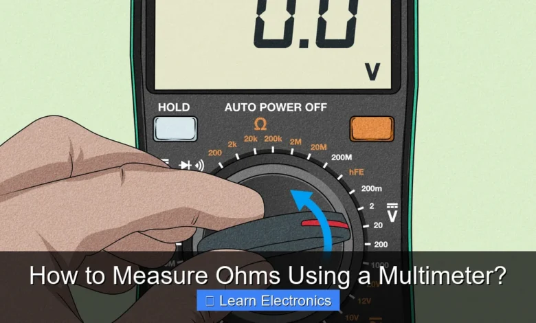
Which setting on my multimeter should I use to measure ohms?
Look for the Omega symbol (Ω) on your multimeter’s dial, which denotes resistance. Set your dial to this symbol and select an appropriate range if your meter isn’t auto-ranging to begin to measure ohms using a multimeter effectively.
What does a reading of “OL” or “1” mean when I’m trying to measure ohms?
An “OL” (Over Limit) or a “1” on the far left of the display typically indicates an open circuit or very high resistance, meaning there’s a break or no complete path for current. This often means the component is faulty, or you might need to select a higher range on your multimeter to measure ohms using a multimeter properly.
📑 Table of Contents
- Understanding Resistance and Your Multimeter
- Preparing Your Multimeter for Measuring Ohms
- Step-by-Step Guide to Measuring Resistance
- Practical Applications and Tips for Measuring Ohms
- Common Pitfalls and Troubleshooting Resistance Readings
- Understanding Resistor Color Codes (Relevant Data)
- Conclusion
Understanding Resistance and Your Multimeter
Before you dive into measuring, it’s vital to grasp what resistance is and how your multimeter works. Resistance, measured in ohms (Ω), is the opposition to the flow of electric current in a circuit. Every material offers some level of resistance, and components like resistors are specifically designed to provide a precise amount. High resistance means less current flows, while low resistance allows more current to pass through.
What is Resistance?
In simple terms, resistance is like a bottleneck in a water pipe; it restricts the flow. In electronics, this restriction is often deliberate and necessary to control current and voltage within a circuit. For instance, resistors are used to limit current to LEDs, while a faulty component might exhibit abnormally high or low resistance, indicating a problem.
Introduction to Multimeters
A multimeter is a versatile electronic measuring instrument that combines several measurement functions in one unit. For our purpose, the resistance (ohms) function is key. Multimeters come in two main types:
- Digital Multimeters (DMMs): These are the most common type today, featuring an LCD screen that displays readings directly as numerical values. They are generally more accurate and easier to read.
- Analog Multimeters: These use a needle and a scale for readings. While still useful, they require more skill to interpret accurately and may need manual calibration (zeroing) more frequently.
Both types have a rotary dial for selecting the measurement function (volts, amps, ohms) and ranges, along with ports for connecting test probes (usually red for positive and black for negative/common).
Preparing Your Multimeter for Measuring Ohms
Proper preparation is key to accurate resistance measurements and ensuring the safety of both yourself and your equipment. Always ensure the device or component you are testing is completely de-energized.
Selecting the Correct Range
On your multimeter’s rotary dial, locate the symbol for ohms (Ω), which often looks like a horseshoe or the Greek letter Omega. Many modern digital multimeters have an “auto-ranging” feature, meaning they automatically select the appropriate resistance range. If your multimeter is manual ranging, you’ll need to select a range. Start with a higher range (e.g., 20kΩ or 200kΩ) if you don’t know the approximate resistance, and then decrease it if the reading is too low (e.g., “OL” or “1” on the display). An “OL” (Over Load) reading usually means the resistance is higher than the selected range can measure, while a very low number (like 0.00) might indicate it’s lower than the current range can precisely resolve.
Calibrating or Zeroing Your Multimeter
For analog multimeters, you’ll typically need to “zero” the ohmmeter before taking a reading. This involves touching the red and black probes together and adjusting a knob (often labeled “Ohms Adjust” or “Zero Adjust”) until the needle points exactly to zero ohms on the resistance scale. This compensates for internal battery voltage fluctuations.
Digital multimeters usually don’t require manual zeroing for resistance, but it’s good practice to touch the probes together; the display should read very close to 0 Ω (e.g., 0.1 Ω or 0.2 Ω). This confirms the probes are working and not adding significant resistance to your measurement.
Step-by-Step Guide to Measuring Resistance
Follow these steps carefully to ensure accurate and safe resistance measurements. The process of using this technique is straightforward once you understand the basic principles.
Safety First: Disconnecting Power
This is the most critical step. Never measure resistance on a live circuit. Applying voltage to an ohmmeter can damage the meter or even create a safety hazard. Always:
- Turn off all power to the circuit or component you intend to test.
- Unplug the device from its power source.
- If possible, remove the component from the circuit entirely. If you must test in-circuit, be aware that parallel components can affect your reading.
- Discharge any large capacitors in the circuit, as they can store significant energy.
Connecting the Probes
Once power is safely off, insert your test probes into the multimeter. The black probe typically goes into the “COM” (common) jack, and the red probe goes into the jack labeled “VΩmA” or similar (indicating voltage, ohms, and milliamps). Then, touch the metal tips of the red and black probes to the two points across the component or section of the circuit where you want to measure resistance. It doesn’t matter which probe goes on which side for resistance measurement.
Interpreting the Reading
Look at your multimeter’s display. The number shown, followed by the unit (Ω, kΩ, or MΩ), is your resistance reading. For example:
- “100 Ω” means 100 ohms.
- “1.5 kΩ” means 1.5 kilo-ohms, or 1,500 ohms.
- “2.2 MΩ” means 2.2 mega-ohms, or 2,200,000 ohms.
If you see “OL” or “1.” on a digital multimeter, it indicates an open circuit (infinite resistance) or that the resistance is higher than the selected range. If you get a reading very close to zero, it indicates a short circuit or very low resistance.
Practical Applications and Tips for Measuring Ohms
Understanding how to measure ohms allows for various diagnostic and verification tasks in electronics. This technique is invaluable for many common troubleshooting scenarios.
Checking Continuity
Continuity is a specific application of resistance measurement. It determines if there’s an unbroken electrical path between two points. Most multimeters have a dedicated continuity setting, often indicated by a speaker symbol, which beeps if the resistance is very low (indicating a continuous path). To check continuity:
- Set your multimeter to the continuity or lowest resistance (Ω) range.
- Touch the probes to the two points you want to check.
- A beep or a reading very close to 0 Ω (typically less than 1-5 Ω) indicates continuity. No beep or “OL” means an open circuit.
This is useful for checking fuses, wires, switch contacts, and PCB traces.
Testing Resistors
You can verify a resistor’s value by directly measuring it. Compare your reading to the resistor’s marked value (using color codes or numerical markings). Keep in mind that resistors have a tolerance (e.g., ±5%), so your reading should be within that range of the stated value.
Diagnosing Circuits
Resistance measurements can help identify faults like:
- Open Circuits: A wire or component that has broken will show “OL” or very high resistance.
- Short Circuits: An unintended low-resistance path, often caused by components touching or damaged insulation, will show very low resistance, often close to 0 Ω.
- Faulty Components: Capacitors, inductors, diodes, and even transistors can sometimes be partially diagnosed by their resistance characteristics (though other multimeter functions are often needed for full testing).
Tips for Accurate Readings
- Avoid Touching Probes: Your body has resistance, and touching the metal tips of the probes during measurement can affect readings, especially for high-resistance components.
- Isolate Components: Whenever possible, desolder one lead of the component from the circuit. This prevents other parallel components from influencing your resistance reading.
- Clean Contacts: Dirt, corrosion, or oxidation on component leads or probe tips can lead to inaccurate, higher resistance readings.
- Stable Connections: Ensure a firm, steady contact between the probes and the component. Loose connections can cause fluctuating or incorrect readings.
- Consider Temperature: The resistance of some materials changes with temperature. For critical measurements, ensure components are at room temperature.
Common Pitfalls and Troubleshooting Resistance Readings
Even with careful preparation, you might encounter unexpected readings. Understanding common issues can help you troubleshoot effectively.
Incorrect Readings and Why
If your multimeter displays an “OL” when you expect a low resistance, or a very low value when you anticipate high resistance, consider these possibilities:
- Wrong Range Selected: On a manual ranging multimeter, if the resistance is outside the selected range, you’ll get an “OL” (too high) or a meaningless low number (too low). Adjust the range.
- Component Still in Circuit: As mentioned, parallel components can skew readings. Always try to test components out of circuit.
- Capacitor Charge: If you’re testing a circuit with capacitors, a charged capacitor can temporarily show a low resistance reading as it discharges through the multimeter, then gradually rise.
- Faulty Probes or Leads: Worn or broken test leads can introduce resistance or create intermittent connections, leading to erratic readings. Test your leads by checking continuity across them.
- External Interference: Strong electromagnetic fields can sometimes interfere with sensitive measurements, although this is less common for basic resistance tests.
Open vs. Short Circuits
These are two common circuit faults that resistance measurements quickly identify:
- Open Circuit: An open circuit means there is a break in the path, preventing current flow. When you measure across an open circuit (e.g., a broken wire or blown fuse), your multimeter will display “OL” (Over Limit) or “1.” (indicating infinite resistance).
- Short Circuit: A short circuit is an unintended, very low-resistance path that allows current to bypass its intended route, often leading to excessive current flow. When you measure across a short circuit, your multimeter will show a reading very close to 0 Ω (e.g., 0.1 Ω or 0.0 Ω).
Differentiating between these two extremes is a fundamental troubleshooting step that can pinpoint major circuit flaws.
Understanding Resistor Color Codes (Relevant Data)
While not a direct measurement, knowing resistor color codes is highly relevant to validating your resistance measurements. It helps you anticipate what value your multimeter should display, thereby confirming both the component’s integrity and your measurement technique.
Here’s a quick reference table for the standard 4-band resistor color code:
| Color | 1st Band (Digit) | 2nd Band (Digit) | Multiplier | Tolerance |
|---|---|---|---|---|
| Black | 0 | 0 | 1 Ω | |
| Brown | 1 | 1 | 10 Ω | ±1% |
| Red | 2 | 2 | 100 Ω | ±2% |
| Orange | 3 | 3 | 1 kΩ | |
| Yellow | 4 | 4 | 10 kΩ | |
| Green | 5 | 5 | 100 kΩ | ±0.5% |
| Blue | 6 | 6 | 1 MΩ | ±0.25% |
| Violet | 7 | 7 | 10 MΩ | ±0.1% |
| Gray | 8 | 8 | ||
| White | 9 | 9 | ||
| Gold | 0.1 Ω | ±5% | ||
| Silver | 0.01 Ω | ±10% |
To use the table, read the first two color bands as digits, the third band as a multiplier, and the fourth band as tolerance. For example, a resistor with bands Red-Violet-Orange-Gold would be 2 (Red) 7 (Violet) x 1kΩ (Orange) with ±5% (Gold) tolerance, equating to 27 kΩ ±5%.
Conclusion
Measuring resistance using a multimeter is a fundamental skill in electronics that empowers you to diagnose problems, test components, and understand circuit behavior. By following the correct safety procedures, preparing your multimeter properly, and understanding how to interpret readings, you can effectively use this tool to troubleshoot a wide array of electrical and electronic systems. Whether you’re checking for continuity, verifying a resistor’s value, or pinpointing an open or short circuit, the process of accurately measuring ohmic values is an indispensable technique that will serve you well in your electronics endeavors.
Frequently Asked Questions
What are ohms and why is it important to measure resistance?
Ohms (Ω) are the unit of electrical resistance, which is a measure of how much an object opposes the flow of electric current. Measuring resistance helps in troubleshooting circuits, checking the integrity of components like wires and resistors, and ensuring proper circuit operation. It’s crucial for diagnosing faults and verifying component specifications.
How do I set up my multimeter to measure ohms?
First, ensure the circuit or component you’re testing is completely de-energized. Plug the black test lead into the common (COM) jack and the red test lead into the jack labeled with an omega symbol (Ω) or sometimes ‘VΩmA’. Then, turn the multimeter’s rotary dial to the resistance (Ω) setting, choosing an appropriate range if your multimeter isn’t auto-ranging.
What is the correct procedure for measuring resistance with a multimeter?
After setting up your multimeter, touch the two probes to the two points across the component or part of the circuit where you want to measure resistance. Ensure the probes make good contact. The multimeter display will then show the resistance value in ohms, kilohms (kΩ), or megohms (MΩ).
Can I measure ohms on a live circuit?
No, you should never attempt to measure ohms on a live or powered circuit. Doing so can provide inaccurate readings, damage your multimeter, or even create a safety hazard. Always ensure that the circuit or component is completely de-energized and disconnected from any power source before performing a resistance measurement.
What does it mean if my multimeter displays “OL” or “1” when measuring ohms?
An “OL” (Overload) or “1” on the far left of the display typically indicates that the measured resistance is higher than the selected range or that there is an open circuit. This means there’s a break in the circuit, infinite resistance, or that the component you’re testing has a very high resistance value beyond the meter’s current setting. If not auto-ranging, try selecting a higher resistance range.
How do I select the appropriate range for measuring ohms on a manual ranging multimeter?
If your multimeter isn’t auto-ranging, start with the highest resistance range available. If you get a reading, move down to the next lower range until you get the most precise reading without the display showing “OL” or “1”. For example, if you expect a low resistance, you might start with 2kΩ, but if you get OL, move to 20kΩ, then 200kΩ and so on, until you get a valid number.
As an Amazon Associate, I earn commission from qualifying purchases.


