How to Test a Circuit Board? Testing a circuit board involves a systematic approach combining visual inspection, power-off measurements, and power-on diagnostics using specialized tools to identify faults. This comprehensive process ensures the functionality and reliability of electronic assemblies before deployment or during troubleshooting. Mastering this technique is crucial for anyone involved in electronics repair, development, or manufacturing.
Proper evaluation of these complex electronic components requires patience, precision, and adherence to safety protocols. Whether you’re a hobbyist or a professional, understanding the stages of circuit board testing will significantly improve your diagnostic capabilities.
Quick Answers to Common Questions
What’s the very first thing I should do when I want to test a circuit board?
A great first step for how to test a circuit board is a thorough visual inspection! Before powering anything on, look for obvious damage like burn marks, bulging capacitors, or broken traces.
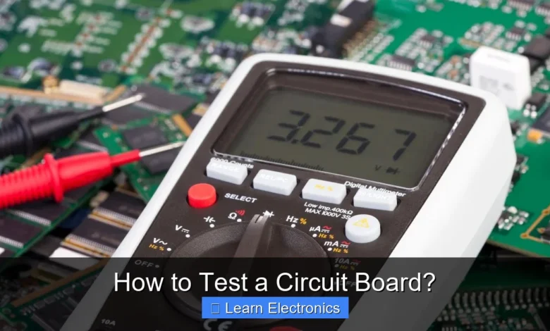
What are the must-have tools for testing a circuit board?
You’ll definitely want a multimeter for checking continuity, voltage, and resistance; it’s absolutely essential for effective circuit board testing. For more advanced diagnostics, an oscilloscope can be incredibly helpful for analyzing signals.
How can I identify a faulty component on my circuit board?
You can often identify faulty components by using your multimeter to check for incorrect resistance values, open circuits, or short circuits, comparing your readings against the component’s expected specifications.
📑 Table of Contents
- Essential Tools and Safety Precautions for Circuit Board Testing
- Pre-Test Visual Inspection: The First Line of Defense
- Power-Off Testing (Continuity and Resistance)
- Power-On Testing and Signal Analysis
- Common Faults and Troubleshooting Strategies for Testing a Circuit Board
- Advanced Testing Techniques and Considerations for Testing a Circuit Board
- Conclusion
Essential Tools and Safety Precautions for Circuit Board Testing
Before beginning any diagnostic work, it’s paramount to equip yourself with the right tools and adhere to strict safety guidelines. The accuracy of your testing and your personal safety depend on it. Investing in quality instruments will not only make the process easier but also yield more reliable results.
Basic Tools for Initial Checks
- Digital Multimeter (DMM): An indispensable tool for measuring voltage, current, resistance, and continuity. Look for one with auto-ranging capabilities and good accuracy.
- Oscilloscope: Essential for visualizing waveforms, measuring frequencies, and observing signal integrity in dynamic circuits. A two or four-channel model is generally sufficient for most tasks.
- Bench Power Supply: A variable DC power supply is crucial for safely powering the circuit board, allowing you to control voltage and current limits to prevent further damage.
- Logic Analyzer: For digital circuits, a logic analyzer can capture and display multiple digital signals simultaneously, helping to debug communication protocols and state machines.
- Magnifying Lamp or Microscope: To aid in the visual inspection of tiny components and solder joints.
- ESD-Safe Mat and Wrist Strap: Critical for preventing electrostatic discharge, which can permanently damage sensitive electronic components.
Prioritizing Safety During the Testing Process
Safety should always be your top concern when working with electronics. Electrical hazards and component damage are real risks if proper precautions are not taken. Always ensure your workspace is well-lit and organized.
- Electrostatic Discharge (ESD) Protection: Always use an ESD-safe wrist strap connected to an ESD mat, which in turn is grounded. This prevents static electricity from damaging sensitive ICs.
- Eye Protection: Wear safety glasses to protect your eyes from accidental solder splashes, component explosions, or chemical exposure.
- Power Off Before Touching: Never touch components or make connections on a powered circuit unless explicitly required for a measurement and you are confident in your setup. Always unplug the power supply first.
- Proper Ventilation: If you are soldering or using chemical cleaners, ensure adequate ventilation to avoid inhaling fumes.
- Isolation Transformer: For testing circuits connected directly to AC mains, an isolation transformer can provide a critical safety barrier against electric shock.
Pre-Test Visual Inspection: The First Line of Defense
Before applying any power or connecting any test equipment, a thorough visual inspection is often the fastest and most effective first step in identifying circuit board issues. Many common faults are visible to the naked eye or with the aid of a magnifying glass.
What to Look For
- Burn Marks or Discoloration: Indicate overheating, often due to excessive current or short circuits.
- Bulging or Leaking Capacitors: Electrolytic capacitors are prone to failure and often show physical signs like bulging tops or fluid leakage.
- Cracked or Chipped Components: Resistors, capacitors, or ICs can be physically damaged, especially from impact or improper handling.
- Cold Solder Joints: Dull, grey, or cracked solder joints that do not make good electrical contact. These often look like small craters or have a rough texture.
- Lifted Traces or Pads: Copper traces or component pads that have delaminated from the PCB substrate, usually due to excessive heat or mechanical stress.
- Missing or Incorrect Components: Compare the board to a known good sample or a schematic to check for missing parts or incorrectly installed components (e.g., wrong orientation of ICs or diodes).
- Contamination: Dust, dirt, corrosion, or foreign objects can cause short circuits or signal interference.
Magnification and Lighting
Utilize a good quality magnifying lamp, jeweler’s loupe, or even a USB microscope to scrutinize fine details. Proper lighting, ideally shadow-free, is essential to reveal subtle defects that might otherwise be overlooked. Pay close attention to areas around power components, connectors, and high-density ICs.
Power-Off Testing (Continuity and Resistance)
Once the visual inspection is complete and no obvious faults are found, the next step is to perform passive tests without applying power to the board. This method helps in detecting short circuits, open circuits, and component failures using a digital multimeter.
Continuity Checks
Set your DMM to continuity mode. This mode typically emits a beep when a low-resistance connection (a short) is detected. It’s excellent for verifying if a trace is intact or if two points that shouldn’t be connected are indeed shorted.
- Verify Traces: Check continuity between points that should be connected, like a component lead and its destination on the board.
- Detect Shorts: Check for continuity between adjacent traces, power and ground planes, or between pins of an IC that shouldn’t be shorted. A beep indicates a potential short.
- Fuse Testing: Always check fuses for continuity. A good fuse will show continuity, while a blown fuse will be an open circuit.
Resistance Measurements and Diode Checks
Switch your DMM to resistance (Ohms) mode. This allows you to measure the resistance of components and across various points on the circuit board.
- Component Resistance: Measure resistors directly on the board, comparing readings to their marked values. Keep in mind that other parallel components might affect the reading. Desoldering one leg of a component can give a more accurate reading.
- Diode and Transistor Checks: Use the diode test function on your DMM to check diodes and transistors. For diodes, you should get a voltage drop reading in one direction and an open circuit in the reverse direction. Transistors can be tested similarly by checking the junctions.
- Capacitor Checks: While a DMM can’t measure capacitance directly (unless it has a dedicated capacitance mode), it can help detect shorts or open circuits in capacitors. In resistance mode, a good capacitor will show a momentary drop in resistance as it charges, then return to an open circuit (for an electrolytic) or a very high resistance (for non-electrolytic). A shorted capacitor will show zero resistance.
- Input/Output Resistance: Measure resistance between power and ground rails. A very low resistance (a few ohms) can indicate a short, though some boards naturally have low resistance on power rails due to switching regulators or large ICs. Compare to a known good board if possible.
Power-On Testing and Signal Analysis
Once passive tests are complete and no obvious faults are found, it’s time to apply power to the board. This is where active testing tools like oscilloscopes become invaluable. Always apply power slowly and monitor for smoke, heat, or unusual smells.
Voltage Measurement
Using your DMM in DC voltage mode, verify that all power rails are at their correct voltages. Check voltage regulators’ inputs and outputs, power supply points, and integrated circuit (IC) VCC pins. Deviations can indicate power supply issues or excessive current draw.
- Power Supply Integrity: Confirm the primary input voltage and then check the outputs of all voltage regulators on the board.
- Component Voltages: Measure voltages across active components like op-amps, transistors, and logic gates to ensure they are within their operational ranges.
- Reference Voltages: Check any reference voltage points to ensure stability and accuracy.
Oscilloscope for Signal Integrity
An oscilloscope allows you to visualize electrical signals, revealing characteristics that a DMM cannot. This is crucial for understanding how signals behave over time.
- Clock Signals: Verify the presence and frequency of clock signals, which are vital for digital circuits.
- Data Lines: Observe data signals for correct voltage levels, rise/fall times, and integrity. Look for noise, ringing, or distorted waveforms.
- Analog Signals: Analyze the shape, amplitude, and frequency of analog signals, such as audio or sensor outputs, for any anomalies.
- Power Supply Ripple: Check the DC power rails for AC ripple, which can indicate failing capacitors or poor regulation.
Logic Analyzers for Digital Circuits
When dealing with complex digital systems, especially those with multiple communication protocols (like I2C, SPI, UART), a logic analyzer is indispensable. It captures multiple digital signals simultaneously and can decode protocols, making debugging much faster than using an oscilloscope for many lines.
- Protocol Decoding: Verify data transmission and reception on buses.
- Timing Analysis: Check for timing violations or glitches in digital signals.
- State Analysis: Track the sequence of events in a complex digital system.
Common Faults and Troubleshooting Strategies for Testing a Circuit Board
Understanding common types of circuit board failures and employing a systematic troubleshooting approach are key to efficiently resolving issues. Many faults manifest in predictable ways, making diagnosis easier once you know what to look for.
Identifying Common Circuit Board Faults
This table outlines some frequent issues and how they typically present themselves:
| Fault Type | Symptoms | Typical Testing Method |
|---|---|---|
| Short Circuit | Overheating, component damage, power supply tripping, no power. | Continuity check (power-off), current measurement (power-on). |
| Open Circuit | No signal, component not functioning, unexpected voltage drops. | Continuity check, resistance measurement (power-off). |
| Component Failure (e.g., Capacitor) | Bulging/leaking, poor power filtering, unstable operation, hum. | Visual inspection, DMM capacitance mode, oscilloscope for ripple. |
| Cold Solder Joint | Intermittent functionality, no connection, erratic behavior. | Visual inspection, continuity check, gentle probing. |
| Incorrect Component Value/Orientation | Incorrect functionality, overheating, no operation. | Visual inspection, resistance measurement, schematic comparison. |
| Corrosion/Contamination | Intermittent shorts, signal leakage, component degradation. | Visual inspection, cleaning, continuity check. |
Systematic Troubleshooting Approach
A methodical approach saves time and reduces frustration:
- Define the Problem: What exactly is the circuit board doing or not doing? When did it start?
- Gather Information: Obtain schematics, datasheets, and any relevant documentation.
- Visual Inspection: Always start here.
- Power-Off Checks: Continuity, resistance, diode tests. Look for shorts first.
- Power-On Checks (Cautiously): Apply power, monitor current, measure voltages.
- Signal Tracing: Use an oscilloscope or logic analyzer to follow signals through the circuit, starting from the input and moving towards the output, or vice-versa from the point of failure.
- Divide and Conquer: If a complex circuit, try to isolate sections. If one section works, the problem is likely in another.
- Component Swapping (Last Resort): Only if you have exhausted other options and suspect a specific component. Use known good replacements.
- Document Findings: Keep detailed notes of your tests and observations.
Advanced Testing Techniques and Considerations for Testing a Circuit Board
Beyond basic DMM and oscilloscope usage, several advanced techniques are employed for complex or high-volume circuit board evaluation, particularly in manufacturing or professional repair settings. These methods offer deeper insights into board integrity and functionality.
Functional Testing
This is often the ultimate test. Functional testing involves simulating the circuit board’s operational environment to verify that it performs its intended tasks correctly. This can range from simple LED blink tests to complex communication protocols and data processing tests.
- Test Jigs: Custom-built fixtures that connect to the board’s I/O and provide power, inputs, and monitor outputs.
- Automated Test Equipment (ATE): Sophisticated systems that can perform thousands of tests in seconds, often used in production lines.
- In-Circuit Test (ICT): A type of ATE that uses a “bed of nails” fixture to make contact with individual component pins and traces, testing each component in isolation and verifying connections.
Thermal Imaging for Hot Spots
Infrared thermal cameras can visualize heat distribution across a powered circuit board. Hot spots indicate components drawing excessive current, short circuits, or stressed components. This non-contact method is excellent for quickly pinpointing areas of concern without direct contact.
- Overheating Components: Easily identify ICs, regulators, or resistors that are failing or improperly rated.
- Shorts in Multi-Layer Boards: Thermal imaging can sometimes reveal the location of shorts within inner layers of a PCB by showing localized heating.
Other Advanced Methods
- Automated Optical Inspection (AOI): High-resolution cameras scan the circuit board to check for manufacturing defects such as missing components, incorrect orientation, poor solder joints, or scratches.
- X-ray Inspection: Used to inspect solder joints under Ball Grid Array (BGA) and other hidden components, and to detect internal trace shorts or opens in multi-layer PCBs.
- Boundary Scan (JTAG): A standard for testing interconnects on integrated circuits and circuit boards without requiring physical test points for every pin, making it ideal for highly dense boards.
- Vibration and Environmental Testing: For products designed for harsh environments, testing involves subjecting the circuit board to extreme temperatures, humidity, and vibrations to check its robustness.
Conclusion
Testing a circuit board is a multifaceted process that ranges from simple visual checks to sophisticated automated diagnostics. By systematically approaching the task, starting with safety and basic inspections before moving to powered tests and advanced analysis, you can effectively diagnose and resolve issues. Developing proficiency in these methods is invaluable for anyone working with electronics, ensuring the functionality, reliability, and longevity of circuit boards in a wide array of applications. Continuous learning and adherence to best practices will make the task of circuit board evaluation an efficient and rewarding endeavor.
Frequently Asked Questions
What tools are essential for testing a circuit board?
You’ll primarily need a multimeter to measure voltage, current, and resistance, which is fundamental for initial diagnostics. A magnifying lamp, oscilloscope, and logic analyzer can also be invaluable for more complex circuit board analysis and signal tracing.
How do I perform a basic visual inspection of a circuit board?
Begin by carefully examining the circuit board for any visible signs of damage, such as burnt components, cracked solder joints, corrosion, or bulging capacitors. A magnifying glass can help spot minute defects that are hard to see with the naked eye.
How can I check for continuity and short circuits on a circuit board?
Use a multimeter set to continuity mode to check for unintended shorts between adjacent traces, component pins, or power and ground planes. You can also test for open circuits by verifying current flow along expected paths on the board.
How do I identify a faulty component on a circuit board?
After a visual inspection, use a multimeter to test individual components like resistors, capacitors, and diodes for their correct values or functionality while the board is unpowered. Comparing readings to a working board or component datasheet can help pinpoint discrepancies.
What safety precautions should I take when testing circuit boards?
Always ensure the circuit board is de-energized and any large capacitors are discharged before handling or testing to prevent electrical shocks. Wear appropriate personal protective equipment, such as safety glasses and an anti-static wrist strap, to prevent ESD damage to sensitive components.
As an Amazon Associate, I earn commission from qualifying purchases.


