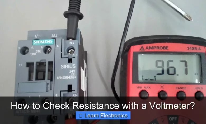
How to Check Resistance with a Voltmeter? This process involves an indirect method, leveraging Ohm’s Law and a known voltage source to calculate an unknown resistance. While voltmeters primarily measure voltage, this technique allows you to infer resistance by understanding current and voltage relationships within a circuit.
This approach is particularly useful when an ohmmeter is unavailable or when measuring resistance in a live circuit context where direct ohmmeter measurement isn’t feasible or safe. It requires careful setup and calculation, but provides a reliable way to determine component resistance.
Quick Answers to Common Questions
Can I really check resistance with a voltmeter directly?
Actually, no, a standard voltmeter doesn’t directly measure resistance like an ohmmeter does. You typically use it to *infer* or *calculate* an unknown resistance by setting up a voltage divider circuit with a known resistor.
What’s the basic idea behind checking resistance with a voltmeter?
You’ll create a simple series circuit using a known reference resistor, the unknown resistance, and a power source. By carefully measuring the voltage drop across either the known resistor or the unknown component, you can then use Ohm’s Law to calculate the unknown resistance.
Why would I use this method instead of an ohmmeter?
This clever technique is super useful when you don’t have an ohmmeter handy, or if you’re trying to troubleshoot a resistance value within a live circuit where an ohmmeter might not be suitable. It’s a great workaround to quickly check resistance with a voltmeter.
📑 Table of Contents
Understanding Resistance and Voltage Measurements
Before diving into the practical steps, it’s crucial to understand what resistance and voltage are, and how they relate. Resistance is the opposition to the flow of electric current in a circuit, measured in Ohms (Ω). Components like resistors are specifically designed to provide a certain amount of resistance.
A voltmeter, on the other hand, measures the electric potential difference, or voltage, between two points in a circuit, expressed in Volts (V). It does this by drawing a tiny amount of current, essentially acting as a very high-resistance path in parallel with the component or section of the circuit being measured.
The key to checking resistance with a voltmeter lies in Ohm’s Law, which states that V = I × R, where V is voltage, I is current, and R is resistance. This fundamental law allows us to derive resistance if we know the voltage across a component and the current flowing through it (R = V / I).
Since a standard voltmeter cannot directly measure current, nor can it directly measure resistance, we must construct a circuit that allows us to infer the current or use voltage ratios to find the unknown resistance. This indirect method is commonly achieved through a voltage divider configuration.
Essential Tools and Safety Precautions
To successfully perform this indirect resistance measurement, you’ll need a few basic tools and a strong understanding of safety protocols.
Required Equipment
- Digital Multimeter (DMM): This is your primary tool, which you will set to its DC voltage measurement function. Ensure it’s calibrated and has good battery life for accurate readings.
- Known Resistor (Rknown): You need a resistor with a precisely known value. Ideally, its resistance should be in the same order of magnitude as the unknown resistor you intend to measure for better accuracy.
- DC Voltage Source: A stable power source is critical. This could be a small battery (e.g., 9V, AA batteries in series) or a variable DC power supply. The voltage should be consistent and sufficient to produce measurable voltage drops across your resistors.
- Resistor to be Measured (Runknown): The component whose resistance you want to determine.
- Breadboard and Jumper Wires: For easily building and modifying your test circuit.
- Alligator Clip Leads: Useful for connecting your voltmeter probes securely.
Safety First: Important Precautions
Electrical work, even with low voltages, always carries risks. Adhere to these safety guidelines:
- Power Off: Always ensure your power source is disconnected or turned off when building or modifying your circuit.
- Check Voltage Ratings: Never apply a voltage source that exceeds the rating of your components or multimeter. For typical hobby electronics, keeping voltages under 20V DC is generally safe.
- Insulated Tools: Use tools with insulated handles to prevent accidental shorts or shocks.
- Avoid Short Circuits: Be meticulous with your wiring. Accidental short circuits can damage your power supply, components, or even cause fires.
- Verify Connections: Double-check all connections before applying power.
- Wear Safety Goggles: Especially when working with power supplies or components that might overheat.
Preparing for the Process of Checking Resistance with a Voltmeter
Before you even begin wiring, ensure your multimeter is functioning correctly in voltage mode. Set it to a DC voltage range appropriate for your power source (e.g., 20V DC range if using a 9V battery). Gather all your components and organize your workspace to avoid clutter and potential errors.
The Voltage Divider Method: The Core Technique
The most common and effective way to determine resistance using a voltmeter is by employing the voltage divider method. This technique relies on creating a series circuit with your unknown resistor and a known resistor, then measuring the voltage drops across each. Because they are in series, the current flowing through both resistors is the same.
Understanding the Principle
When two resistors (Rknown and Runknown) are connected in series to a voltage source (Vsource), the total voltage is divided between them in proportion to their resistances. The total current (Itotal) flowing through the series circuit can be found using Ohm’s Law:
Itotal = Vsource / (Rknown + Runknown)
The voltage drop across the unknown resistor (Vunknown) would then be:
Vunknown = Itotal × Runknown
By substituting Itotal into the second equation, we get the voltage divider formula:
Vunknown = Vsource × (Runknown / (Rknown + Runknown))
Our goal is to find Runknown. We can rearrange this formula or, more practically, use the ratio of voltage drops:
Since the current (I) is the same through both resistors in a series circuit:
I = Vknown / Rknown
and
I = Vunknown / Runknown
Therefore:
Vknown / Rknown = Vunknown / Runknown
Rearranging to solve for Runknown:
Runknown = Rknown × (Vunknown / Vknown)
This formula is generally the easiest to apply, as it only requires you to measure Vunknown and Vknown (and know Rknown).
Performing the Measurement: A Step-by-Step Guide
Let’s walk through the actual process of setting up the circuit and taking measurements.
Setting Up Your Circuit Safely
- Identify Components: Have your known resistor (e.g., 1 kΩ), your unknown resistor, a stable DC voltage source (e.g., 9V battery), and your multimeter ready.
- Assemble Series Circuit: On your breadboard, connect the known resistor and the unknown resistor in series. This means one lead of the known resistor connects to one lead of the unknown resistor.
- Connect to Power Source: Connect the remaining free lead of the known resistor to the positive (+) terminal of your DC voltage source. Connect the remaining free lead of the unknown resistor to the negative (-) terminal of your DC voltage source.
- Verify Connections: Double-check that all connections are secure and correct. Ensure no bare wires are touching unintentionally, which could create a short circuit.
Using Your Voltmeter Correctly
- Set Multimeter: Turn on your multimeter and set it to the DC voltage (V DC or V—) setting. Choose a range appropriate for your source voltage (e.g., 20V range for a 9V battery).
- Apply Power: Now, connect your DC voltage source to the circuit.
- Measure Vsource (Optional but Recommended): First, measure the voltage directly across your power source to confirm its actual output. Place the red probe on the positive terminal and the black probe on the negative terminal. Record this value (Vsource).
- Measure Vunknown: Place the red (positive) probe of your voltmeter across one lead of the unknown resistor and the black (negative) probe across the other lead of the unknown resistor. Ensure the probes are in parallel with the resistor. Read and record the voltage displayed on your multimeter (Vunknown).
- Measure Vknown: Similarly, place the red probe across one lead of the known resistor and the black probe across the other lead. Read and record this voltage (Vknown).
- Disconnect Power: Always disconnect the power source immediately after taking your measurements to conserve battery life and prevent component heating.
Calculating the Unknown Resistance
Once you have your voltage readings and the value of your known resistor, you can calculate Runknown using the formula:
Runknown = Rknown × (Vunknown / Vknown)
Example Calculation:
Let’s say:
- Rknown = 1000 Ω (1 kΩ)
- Vsource = 9.0 V (measured)
- Vunknown = 4.5 V (measured across the unknown resistor)
- Vknown = 4.5 V (measured across the known resistor)
Using the formula:
Runknown = 1000 Ω × (4.5 V / 4.5 V)
Runknown = 1000 Ω × 1
Runknown = 1000 Ω
In this symmetrical case, both resistors are 1kΩ. If the values were different, the ratio would reflect that.
Alternatively, if you only measured Vsource and Vunknown, you can calculate Vknown:
Vknown = Vsource - Vunknown
Then apply the main formula. For instance, if Vsource = 9V and Vunknown = 3V, then Vknown = 9V – 3V = 6V. If Rknown = 1000 Ω:
Runknown = 1000 Ω × (3 V / 6 V)
Runknown = 1000 Ω × 0.5
Runknown = 500 Ω
Practical Tips, Accuracy, and Limitations
While the voltage divider method is effective, its accuracy depends on several factors. Here are some tips and considerations:
Choosing the Right Known Resistor
For the best accuracy, the known resistor (Rknown) should be of a similar magnitude to the unknown resistor (Runknown). If Rknown is much larger or smaller than Runknown, the voltage drop across one of them will be very small, potentially falling outside the most accurate range of your voltmeter or leading to larger measurement errors.
- If Runknown is expected to be around 1 kΩ, use a 1 kΩ known resistor.
- If Runknown is expected to be in the tens of kΩ, use a 10 kΩ or 20 kΩ known resistor.
Ensuring Accurate Readings
- Stable Voltage Source: Fluctuations in your power supply will lead to inaccurate voltage readings. Use fresh batteries or a regulated power supply.
- Good Connections: Loose or poor connections can introduce unwanted resistance or voltage drops, skewing your results. Ensure all wires and probes make solid contact.
- Meter Resolution: Use a multimeter with sufficient resolution (e.g., enough decimal places) for your expected voltage readings.
- Component Tolerance: Remember that even your known resistor has a tolerance (e.g., 1%, 5%). This inherent inaccuracy will affect your calculated Runknown. For high precision, use precision resistors for Rknown.
- Temperature Effects: Resistance of most materials changes with temperature. Allow components to cool if they’ve been used in a circuit that generates heat.
Limitations of the Method
While invaluable, this technique has limitations compared to a dedicated ohmmeter:
- Indirect Measurement: It requires calculation and is not a direct reading, increasing the potential for human error.
- Requires External Components: You need a known resistor and a stable voltage source, which may not always be readily available.
- Not for All Resistance Ranges: It becomes difficult to measure extremely low or extremely high resistances accurately using this method due to voltage drop limitations and the practical choice of Rknown.
- Slower than an Ohmmeter: For quick checks, an ohmmeter is far more convenient.
- Not for In-Circuit Resistance of Complex Circuits: This method works best for isolated resistors or simple series circuits. Measuring resistance in complex circuits while powered can be misleading due to parallel paths and active components.
Data Table for Example Measurements
Here’s an example of how you might record your measurements and calculations:
| Parameter | Value | Unit |
|---|---|---|
| Known Resistor (Rknown) | 1000 | Ω |
| Source Voltage (Vsource) | 8.8 | V |
| Voltage across Unknown Resistor (Vunknown) | 3.2 | V |
| Voltage across Known Resistor (Vknown) | 5.6 | V |
| Calculated Unknown Resistor (Runknown) | 571.43 | Ω |
Calculation for the table: Runknown = 1000 × (3.2 / 5.6) ≈ 571.43 Ω
Conclusion
While an ohmmeter is the tool of choice for direct resistance measurement, knowing how to check resistance with a voltmeter through the voltage divider method is a valuable skill in electronics. This indirect technique provides a practical solution when you need to determine an unknown resistance using readily available tools and fundamental circuit principles. By understanding Ohm’s Law, carefully setting up your series circuit, taking accurate voltage readings, and performing the necessary calculations, you can reliably ascertain resistance values. Always prioritize safety, choose appropriate components, and be mindful of the limitations to achieve the most accurate results in your electronics projects.
Frequently Asked Questions
Can I really check resistance with a voltmeter, or do I need an ohmmeter?
While a voltmeter directly measures voltage and an ohmmeter is designed for resistance, you can *indirectly* determine resistance using a voltmeter, a known voltage source, and by measuring current. This method relies on Ohm’s Law (R=V/I) and requires a bit more setup than a dedicated ohmmeter.
What other tools do I need to measure resistance using a voltmeter?
To measure resistance indirectly with a voltmeter, you’ll also need a stable DC power supply (like a battery) and an ammeter to measure the current flowing through the component. Alternatively, if you have a known reference resistor and measure voltage drops, you can deduce the unknown resistance.
What is the basic principle for checking resistance with a voltmeter?
The basic principle involves applying a known voltage across the component whose resistance you want to measure and then measuring the resulting current. By using Ohm’s Law, Resistance (R) = Voltage (V) / Current (I), you can calculate the resistance. You would use your voltmeter to measure the voltage and an ammeter for the current.
How accurate is this method compared to using an ohmmeter for resistance checks?
This indirect method of checking resistance with a voltmeter can be less accurate than using a dedicated ohmmeter, especially for very small or very large resistances. Its accuracy depends heavily on the precision of your voltmeter and ammeter, and the stability of your power source. Ohmmeter devices are designed to provide a more direct and often more precise measurement.
Are there situations where checking resistance with a voltmeter is preferable?
This method can be useful when you don’t have an ohmmeter available but do have a voltmeter, an ammeter, and a power supply. It’s also sometimes employed in troubleshooting live circuits where you can measure voltage and current to infer a component’s resistance under operating conditions, which an ohmmeter cannot do directly.
As an Amazon Associate, I earn commission from qualifying purchases.


