How to Check a Circuit Board? involves a systematic approach combining visual inspection, basic continuity tests, and advanced component analysis to diagnose malfunctions. This technique helps pinpoint failures in electronic devices, saving time and resources. Mastering this method allows hobbyists and professionals to identify issues ranging from simple broken traces to faulty integrated circuits, ensuring efficient repair or replacement and extending the lifespan of valuable electronics.
Successfully performing circuit board diagnostics requires patience, attention to detail, and a good understanding of electronic components. The process outlined here provides a comprehensive guide for anyone looking to troubleshoot and understand the health of their PCBs.
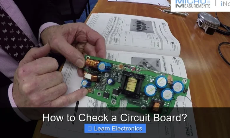
Starting the Diagnosis: How to Check a Circuit Board Visually
Before diving into electrical tests, a thorough visual inspection is your first and often most effective step in identifying obvious issues. Many common problems, such as burnt components or poor solder joints, are visible to the naked eye or with a magnifying glass.
- Examine for Discoloration or Burns: Look for any areas that appear darker or charred. Burn marks often indicate overheating, short circuits, or components that have failed catastrophically. Resistors, capacitors, and ICs are common culprits.
- Inspect Capacitors: Electrolytic capacitors are notorious for physical failure. Look for bulging tops or bottoms, leakage (often a brownish crust), or distorted casings. A visibly damaged capacitor is almost certainly a faulty one.
- Check Solder Joints: Cold solder joints (dull, grainy, or cracked appearance instead of shiny and smooth) and solder bridges (unintended connections between two solder points) can cause intermittent or complete circuit failures. Pay close attention around pins of ICs and connectors.
- Look for Cracks or Damage: Physical impact can crack the board itself, breaking traces (the copper pathways) or damaging components. Flex the board gently (if appropriate for the device) to see if any cracks become more apparent.
- Identify Swollen ICs or Components: Integrated circuits (ICs), transistors, and diodes can sometimes swell or show signs of physical stress when they fail due to overcurrent or overheating.
- Trace Examination: Use a magnifying glass to follow traces from components to their destinations. Look for any breaks, corrosion, or lifted traces that could interrupt the electrical path.
This initial visual sweep can often lead you directly to the source of a problem, significantly streamlining the diagnostic process. Documenting your observations, even with simple notes or photos, can be helpful for later reference or if you need to consult with others.
Quick Answers to Common Questions
What’s the very first thing I should check on a circuit board?
Always start with a thorough visual inspection! Look closely for any obvious damage like burn marks, bulging capacitors, corroded traces, or broken components on your *circuit board* – these are often tell-tale signs of trouble.
Do I need fancy equipment to test a circuit board?
Not necessarily, but a multimeter is your best friend! It’s an indispensable tool for checking continuity, voltage, and resistance across your *circuit board* to pinpoint specific issues.
How can I tell if a specific component on my circuit board is faulty?
After a visual check, grab your multimeter. You can test individual components like resistors, capacitors, or diodes for correct values, opens, or shorts to diagnose the exact problem on your *circuit board*.
📑 Table of Contents
Essential Tools for Effective Circuit Board Analysis
To accurately assess the health of a circuit board and perform detailed diagnostic steps, you’ll need a basic set of tools. Investing in quality equipment will make the job easier and more reliable.
- Digital Multimeter (DMM): This is your most crucial tool. A DMM can measure voltage (AC/DC), current (amps), resistance (ohms), and often continuity. Some models also include capacitance and diode test functions.
- Magnifying Glass or Microscope: Essential for close inspection of small components, solder joints, and fine traces. A jeweler’s loupe or a USB microscope can be incredibly useful.
- Soldering Iron and Supplies: While primarily for repair, a soldering iron, solder, desoldering braid/pump, and flux are vital if you plan to replace faulty components.
- Tweezers and Probes: Fine-tipped tweezers help manipulate small components. Specialized multimeter probes (e.g., alligator clips, sharp tips) can make testing easier and safer.
- Bench Power Supply (Optional but Recommended): A variable DC power supply allows you to safely power up a circuit board with controlled voltage and current, helping identify shorts without damaging more components.
- Oscilloscope (Advanced): For diagnosing more complex issues involving waveforms, signals, and timing, an oscilloscope is invaluable. It displays voltage over time, revealing signal integrity, noise, and timing problems.
- ESD Protection: An anti-static mat, wrist strap, and proper grounding procedures are crucial to prevent electrostatic discharge, which can silently damage sensitive electronic components.
Having these tools ready will equip you for nearly any circuit board diagnostic task, from simple continuity checks to more complex signal analysis.
Basic Electrical Tests: Continuity and Resistance
Once the visual inspection is complete, the next logical step involves using your multimeter to perform fundamental electrical tests. These tests can confirm breaks in connections or identify unintended shorts.
Performing Continuity Checks
Continuity testing determines if an electrical path exists between two points. It’s used to check traces, wires, fuses, and switches.
- Power Off and Discharge: Ensure the circuit board is completely powered off and disconnected from any power source. Discharge any large capacitors by shorting their terminals with a resistor (e.g., 1kΩ) to prevent shocks or damage.
- Set Multimeter: Set your multimeter to the continuity mode (usually indicated by a speaker icon). When the probes touch and there’s a continuous path, the multimeter will beep and display a very low resistance value (near 0 ohms).
- Check Traces: Place one probe on one end of a suspected trace and the other probe on the other end. A beep confirms continuity. If there’s no beep, the trace is broken.
- Test Fuses: Place probes across both ends of a fuse. A good fuse will show continuity. No continuity means the fuse is blown.
- Verify Switches: Test switches in both their open and closed positions to ensure they break and make connections correctly.
Continuity is a binary test – a path either exists or it doesn’t. It’s excellent for quickly identifying open circuits.
Measuring Resistance of Components
Resistance measurement tells you how much a component opposes the flow of current. It’s crucial for testing resistors, identifying shorts, and diagnosing open circuits.
- Power Off and Discharge: As with continuity, ensure no power is present.
- Set Multimeter: Set your multimeter to the resistance mode (Ohms, Ω). Start with a higher range if you’re unsure of the expected resistance, and then reduce it for a more precise reading.
- Test Resistors: Measure across the two leads of a resistor. Compare the reading to its color code or marked value. Keep in mind that other components in parallel on the board can affect the reading. For accurate measurements, it’s often best to desolder one leg of the resistor.
- Check for Shorts: Measure resistance between power and ground planes. A very low resistance (near 0 ohms) could indicate a short circuit. If the board typically consumes low power, a low resistance reading could be normal due to many components in parallel, so comparing to a known good board is helpful.
- Identify Open Circuits: An open circuit will show an “OL” (Over Limit) or infinite resistance reading on the multimeter. This can indicate a broken trace, a blown fuse, or a failed component that has gone open.
Resistance readings can be trickier on an assembled board due to parallel paths. For critical components, isolation might be necessary for accurate testing.
Advanced Diagnostic Techniques and Component Testing
Beyond basic continuity and resistance, a deeper dive into the circuit’s operation involves measuring voltages and currents, and specifically testing various component types. This requires a more nuanced approach.
Voltage and Current Measurements
Measuring voltage and current helps confirm if components are receiving the correct power and if the circuit is drawing appropriate current. This often requires the board to be powered on.
- Safety First: When the board is powered, exercise extreme caution. Avoid touching live circuits with your bare hands and be aware of high voltage areas. Use only one hand for probing if possible, keeping the other hand away to prevent a complete circuit through your body.
- Measure Input Voltage: Verify that the power supply is providing the correct voltage to the board’s input terminals.
- Check Voltage Regulators: Voltage regulators are common failure points. Measure the input and output voltages to ensure they are regulating power correctly.
- Verify Power Rails: Measure the voltage on various power rails (e.g., 3.3V, 5V, 12V) around ICs and other components to ensure they are receiving stable and correct power.
- Measure Current (with Caution): To measure current, the multimeter must be placed in series with the circuit. This usually involves breaking the circuit and inserting the multimeter. Start with a high current range to avoid blowing the fuse in your multimeter. A sudden spike in current could indicate a short.
Incorrect voltage levels, absent power rails, or unusually high/low current draws are strong indicators of a problem. Datasheets for ICs are invaluable here, providing expected voltage levels for different pins.
Testing Specific Components
Different components fail in different ways and require specific testing methods.
- Diodes: Use the multimeter’s diode test function. A healthy diode will show a voltage drop (typically 0.2-0.7V for silicon diodes) in one direction and an open circuit (OL) in the reverse direction. A shorted diode will show 0V in both directions, while an open diode will show OL in both.
- Transistors: Transistors (BJTs and MOSFETs) can be tested using the diode test function to check their junctions, referring to their datasheet for pinouts (Base, Emitter, Collector or Gate, Drain, Source). A shorted or open junction indicates a faulty transistor.
- Capacitors: While visual inspection helps, a multimeter can measure capacitance (if it has the function). An ESR (Equivalent Series Resistance) meter is even better for electrolytic capacitors, as high ESR often indicates failure before visible signs appear.
- Integrated Circuits (ICs): ICs are harder to test directly on the board without specialized equipment. The most common approach is to verify correct supply voltages on their power pins and observe input/output signals with an oscilloscope. If all surrounding components are good and power is correct, a faulty IC is often suspected.
Understanding the Process: How to Check a Circuit Board with a Multimeter
The multimeter is your primary tool for most of these electrical checks. Its versatility allows you to switch between different measurement modes to systematically diagnose problems. Always remember to select the correct measurement type (AC/DC voltage, resistance, continuity, etc.) and range before making a connection. Begin with higher ranges and decrease as needed for accuracy. Proper probe placement and isolation of components when necessary are key to obtaining reliable readings.
Common Circuit Board Problems and Troubleshooting Tips
Understanding common failure modes helps narrow down the diagnostic process. Here’s a summary of typical issues and how to approach them:
| Component Type | Common Failure Symptom | Diagnostic Test | Expected Reading (Good) |
|---|---|---|---|
| Resistor | Incorrect value, open circuit (OL) | Resistance Measurement | Matches color code/marking |
| Capacitor (Electrolytic) | Swollen, bulging, leaking, high ESR, short | Visual Inspection, Capacitance, ESR Meter | No visible damage, matches marking, low ESR |
| Diode | Shorted (0V drop both ways), Open (OL both ways), Leaky | Diode Test (Multimeter) | Forward: 0.2-0.7V, Reverse: OL |
| Transistor | Shorted junctions, Open junctions | Diode Test (Multimeter), Hfe (some DMMs) | Varies by type (PNP/NPN) – check datasheet |
| Fuse | Open circuit (OL) | Continuity Test | Beep / ~0 Ohms |
| Trace/Wire | Discoloration, crack, break | Continuity Test | Beep / ~0 Ohms |
| Voltage Regulator | Incorrect output voltage, overheating | Voltage Measurement (Input/Output) | Stable, regulated output voltage |
| Integrated Circuit (IC) | No output, incorrect function, overheating | Voltage Measurement (Power pins), Signal Analysis (Oscilloscope) | Correct power, expected signals |
- No Power: Start by checking the input power source, fuse, power jack, and then voltage regulators. Use continuity to check for open circuits and resistance to check for shorts between power and ground.
- Intermittent Faults: These are the trickiest. Often caused by cold solder joints, hairline cracks in traces that open under thermal stress, or components that fail when hot. Visual inspection under magnification, gently flexing the board, or heating/cooling suspect components can sometimes reveal the issue.
- Overheating Components: Feel components for excessive heat (carefully!) or use an infrared thermometer. Overheating often points to excessive current draw (short) or a failing component.
- Dead Short: If your power supply immediately trips or shows very high current draw, there’s a dead short. Use resistance mode between power and ground. You can use a bench power supply with current limiting to inject a small, safe current into the short and feel for the component that heats up.
Safety First and Conclusion
Working with electronics, especially powered circuits, demands respect for safety. Always prioritize your well-being. Disconnect power before making resistance or continuity measurements. Be mindful of electrostatic discharge (ESD) and wear appropriate protection. High voltages can be lethal, so if you’re uncomfortable or unsure, seek professional help.
Ultimately, learning to diagnose and troubleshoot circuit boards is a skill honed through practice and experience. By following a systematic approach—starting with visual inspection, moving to basic electrical tests, and then employing more advanced diagnostic techniques—you can effectively pinpoint issues. Remember that every circuit board presents a unique challenge, but with patience and the right tools, you can successfully understand and resolve many electronic malfunctions. The satisfaction of bringing a faulty device back to life through diligent troubleshooting is a rewarding experience for any electronics enthusiast.
Frequently Asked Questions
How do I visually inspect a circuit board for issues?
Begin by performing a thorough visual inspection of the circuit board. Look for any obvious signs of damage such as burnt components, bulging capacitors, cracked traces, or dry/cold solder joints. Good lighting and a magnifying glass will help you spot subtle defects.
What’s the best way to test if a circuit board is receiving power?
To check for power, use a multimeter to measure the voltage at known power input points or voltage regulator outputs on the circuit board. Compare these readings to the expected voltage levels for proper operation. Always ensure the power supply unit itself is functional before attributing power issues to the board.
How can I test individual components on a circuit board?
With the circuit board depowered, use a multimeter to test individual components such as resistors, capacitors, diodes, and transistors. Measure resistance, capacitance, or diode drop and compare readings to component datasheets or the values found on a known good board. Always ensure components are isolated from the rest of the circuit for accurate readings where possible.
How do I check for continuity and trace integrity on a circuit board?
Use a multimeter in continuity mode to check for breaks in traces or faulty solder connections on the circuit board. Place the multimeter probes on two points that should be electrically connected and listen for a beep, indicating continuity. If there’s no beep, it suggests an open circuit or a broken trace that may need repair.
What tools are useful for diagnosing complex circuit board issues?
For more advanced diagnostics on a circuit board, an oscilloscope is crucial for analyzing signal waveforms, frequencies, and timing, helping to identify intermittent faults or signal integrity problems. For digital circuits, a logic analyzer can be used to capture and interpret multiple digital signals simultaneously, aiding in the debugging of microcontrollers and other ICs. These tools provide deeper insight than basic multimeter checks.
As an Amazon Associate, I earn commission from qualifying purchases.


