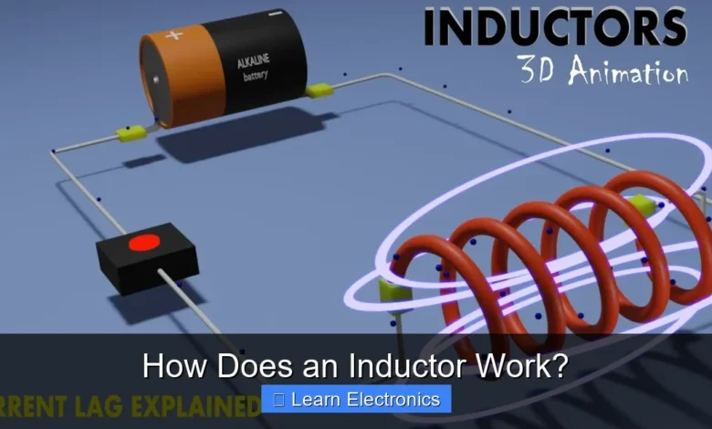
How does an Inductor Work? An inductor primarily works by storing energy in a magnetic field when an electric current flows through it, opposing changes in that current. This fundamental principle of electromagnetic induction allows inductors to filter signals, store energy, and control current flow in a myriad of electronic circuits, making them indispensable components.
This method of operation is crucial for countless applications, from basic power supplies to sophisticated radio frequency systems. Understanding this device’s behavior is key to mastering electronics.
Quick Answers to Common Questions
What exactly does an inductor do?
An inductor’s main job is to store energy in a magnetic field and, more importantly, to oppose any changes in the electric current flowing through it. Think of it as a magnetic energy reservoir or a current stabilizer in a circuit!
Why is an inductor usually just a coil of wire?
The coiled shape is crucial because it concentrates the magnetic field produced by the current, making the inductor much more effective at storing magnetic energy and resisting current changes. This design greatly enhances its ‘inductance’.
How does an inductor resist current changes?
When the current through an inductor tries to change, the changing magnetic field induces a voltage (called back-EMF) that actively opposes that change, effectively acting like “magnetic inertia.” This inherent property is fundamental to how an inductor works to smooth out current fluctuations.
📑 Table of Contents
- The Fundamental Principle: Electromagnetism and Inductance
- An Inductor’s Anatomy: Components and Construction
- Understanding How an Inductor Works with Current Flow
- Key Characteristics Defining Inductor Performance
- Practical Applications: Where Inductors Shine
- Comparing Inductors: Types and Their Properties
- Conclusion
The Fundamental Principle: Electromagnetism and Inductance
At the heart of an inductor’s function lies the intricate dance between electricity and magnetism. When an electric current passes through a wire, it generates a magnetic field around that wire. This phenomenon is known as electromagnetism. The strength and direction of this magnetic field are directly proportional to the current flowing through the wire.
Faraday’s Law and Lenz’s Law: The Inductive Response
The true magic of inductance emerges when the current, and consequently the magnetic field, changes. According to Faraday’s Law of Induction, a changing magnetic field through a coil of wire will induce an electromotive force (EMF), or voltage, across the coil. This induced voltage is proportional to the rate of change of the magnetic flux.
Complementing Faraday’s Law is Lenz’s Law, which states that the direction of this induced EMF will always oppose the change in current that produced it. If the current tries to increase, the inductor generates an opposing voltage to resist that increase. If the current tries to decrease, the inductor generates a voltage to maintain the current flow. This inherent opposition to change is the defining characteristic of an inductor and is often referred to as “electrical inertia.”
The Core Principles of How an Inductor Works
The core principle of how an inductor works involves its ability to store energy in a magnetic field. When current flows, the magnetic field builds up, storing energy. When the current decreases, the magnetic field collapses, releasing its stored energy back into the circuit, often as a voltage spike. This energy storage and release mechanism is fundamental to its applications, particularly in power regulation and filtering.
An Inductor’s Anatomy: Components and Construction
While the principles are abstract, the physical construction of an inductor is quite simple, yet highly effective. It typically consists of a coil of wire, often wrapped around a core material.
The Wire Coil: The Heart of Inductance
The primary component is the conductive wire, usually copper, wound into a coil. The number of turns in the coil, the diameter of the coil, and the spacing between turns significantly influence the inductor’s value. More turns typically result in higher inductance because each turn contributes to the magnetic field, and their fields combine, enhancing the overall effect.
The Core Material: Shaping the Magnetic Field
The material around which the wire is wound, known as the core, also plays a critical role. Cores can be made from various materials, each affecting the inductor’s performance:
- Air Core: Simpler construction, lower inductance values, excellent for high-frequency applications where magnetic saturation is a concern.
- Ferrite Core: Made from ceramic compounds, these cores significantly increase inductance by concentrating magnetic flux. They are common in radio frequency (RF) and switching power supply applications due to their high resistivity and low eddy current losses.
- Iron Core: Laminated iron cores provide even higher inductance values, suitable for low-frequency power applications where large inductances are required, like power supply chokes. However, they are heavier and prone to saturation at lower currents compared to ferrite.
Understanding How an Inductor Works with Current Flow
The behavior of an inductor changes dramatically depending on whether it’s subjected to direct current (DC) or alternating current (AC).
DC Current Behavior: Energy Storage
When an inductor is connected to a DC voltage source, the current doesn’t immediately jump to its maximum value. Instead, the inductor initially opposes the sudden change. As the current begins to flow, a magnetic field builds up around the coil. This building magnetic field induces an opposing voltage (back-EMF) that limits the rate of current increase. Over time, as the magnetic field fully establishes itself, the opposition diminishes, and the inductor acts like a short circuit, allowing current to flow freely (minus the resistance of the wire itself). When the DC source is disconnected, the magnetic field collapses, inducing a voltage spike (often in the opposite direction) as the stored energy is released.
AC Current Behavior: Reactance and Phase Shift
In an AC circuit, the current is constantly changing in magnitude and direction. This continuous change means the inductor is always generating an opposing voltage. This opposition to AC current is called inductive reactance (XL), measured in ohms. Unlike resistance, which dissipates energy as heat, inductive reactance stores and releases energy, causing a phase shift between voltage and current.
Specifically, in a purely inductive circuit, the voltage across the inductor leads the current through it by 90 degrees. The higher the frequency of the AC current, the greater the rate of change, and thus the greater the inductive reactance, effectively making the inductor act like a higher resistance to higher frequencies. This property is vital for filtering applications.
Key Characteristics Defining Inductor Performance
Several parameters define an inductor’s performance and suitability for specific applications.
Inductance (L) and Inductive Reactance (XL)
Inductance (L) is the fundamental property of an inductor, measured in Henries (H). It quantifies the inductor’s ability to store energy in its magnetic field and oppose changes in current. Factors like the number of turns, coil area, coil length, and core material all determine the inductance value.
Inductive Reactance (XL) is the opposition an inductor offers to AC current flow. It is frequency-dependent and calculated using the formula: XL = 2πfL, where ‘f’ is the frequency and ‘L’ is the inductance. This characteristic is crucial for understanding how inductors behave in AC circuits and for designing filters.
Quality Factor (Q) and Saturation
The Quality Factor (Q) of an inductor represents its efficiency. It’s the ratio of its inductive reactance to its inherent series resistance (the resistance of the wire coil). A higher Q factor indicates less energy loss and is desirable for resonant circuits and filters. Q = XL / R.
Saturation occurs when the magnetic core material can no longer support an increase in magnetic flux, even if the current continues to increase. Beyond saturation, the inductance drops sharply, and the inductor behaves more like a simple resistor, losing its intended inductive properties. Designers must select inductors with appropriate saturation current ratings for their applications.
Practical Applications: Where Inductors Shine
The unique properties of inductors make them indispensable in a vast array of electronic circuits.
Filtering and Chokes
Inductors are commonly used as “chokes” in filters. Because they oppose high-frequency AC signals more than low-frequency ones, they can block unwanted noise or ripple while allowing desired signals (like DC or low-frequency AC) to pass. This is vital in power supplies to smooth out rectified AC voltage and in audio circuits to remove hiss or hum.
Energy Storage in Power Supplies
In switching mode power supplies (SMPS) and DC-DC converters (like buck or boost converters), inductors temporarily store energy from the input and then release it to the output at a different voltage level. This process is highly efficient and forms the backbone of modern power conversion.
Resonant Circuits and EMI Suppression
When combined with capacitors, inductors form LC resonant circuits, which are fundamental to radio tuners, oscillators, and filters that select specific frequencies. The combination resonates at a particular frequency, making these circuits selective to certain signals. Inductors also play a role in Electromagnetic Interference (EMI) suppression, where ferrite beads (small inductors) are used to absorb and dissipate high-frequency noise that can interfere with other electronics.
Comparing Inductors: Types and Their Properties
The choice of inductor depends heavily on the specific application’s requirements for inductance, frequency response, current handling, and physical size. Here’s a brief comparison:
Air Core, Ferrite Core, and Iron Core Inductors
Air core inductors offer linearity, meaning their inductance doesn’t change with current, making them ideal for high-frequency RF applications where signal integrity is paramount. However, their inductance values are generally low. Ferrite core inductors provide higher inductance in smaller packages and are excellent for filtering and energy storage in medium-to-high frequency ranges. They are prone to saturation but come in various formulations for different frequency and power needs. Iron core inductors offer the highest inductance values, suitable for low-frequency power applications, but are bulky and heavy, and also susceptible to saturation and core losses at higher frequencies.
Table: Common Inductor Types and Characteristics
| Inductor Type | Core Material | Typical Inductance Range | Primary Applications | Key Characteristics |
|---|---|---|---|---|
| Air Core | Air, plastic formers | nH to µH | RF circuits, high-frequency filters, antennas | Linearity, low loss, low inductance, no saturation |
| Ferrite Core | Ferrite ceramic | µH to mH | Switching power supplies, EMI filters, RF chokes | High inductance/size, good high-frequency performance, susceptible to saturation |
| Iron Core | Laminated iron | mH to H | Power supply chokes, audio crossovers, low-frequency filters | Very high inductance, high current handling, bulky, lower frequency use |
| Toroidal | Ferrite, powdered iron | µH to mH | SMPS, common-mode chokes, RF transformers | Efficient magnetic coupling, compact size, reduced EMI radiation |
The toroidal inductor, listed above, is a specific form factor that can use either ferrite or powdered iron cores, known for its superior magnetic coupling and reduced external magnetic field radiation compared to open-coil types.
Conclusion
From smoothing power lines to tuning radio waves, the inductor is a humble yet powerful component, essential to nearly every electronic system. Its ability to store energy in a magnetic field and inherently oppose changes in current makes it invaluable for filtering, energy conversion, and signal processing. Understanding the core principle of inductor operation and its various characteristics is fundamental for anyone looking to design, troubleshoot, or simply comprehend the inner workings of electronic circuits. As technology advances, inductors continue to evolve, offering improved performance in increasingly compact and efficient forms.
Frequently Asked Questions
What is an inductor and what is its primary function?
An inductor is a passive electrical component that stores energy in a magnetic field when electric current flows through it. Its primary function is to oppose changes in the electric current flowing through it, maintaining current stability within a circuit.
How does an inductor store energy?
When electric current flows through the coil of an inductor, it generates a magnetic field around it. This magnetic field stores energy, which can then be released back into the circuit when the current decreases or attempts to change.
What is inductance and why is it important for an inductor’s operation?
Inductance is the property of an electrical conductor to oppose a change in the electric current flowing through it. It quantifies how much magnetic flux is produced per unit of current, directly determining an inductor’s ability to store energy and resist current changes.
How does an inductor behave differently with alternating current (AC) compared to direct current (DC)?
With direct current (DC), an inductor acts like a short circuit once the current stabilizes, offering very little resistance. However, with alternating current (AC), an inductor continuously opposes the changing current, leading to a significant impedance (resistance to AC) that increases with frequency.
As an Amazon Associate, I earn commission from qualifying purchases.


