How Do You Check a Diode? You can reliably check a diode’s functionality primarily using a digital multimeter (DMM) in its diode test mode or, less precisely, its resistance mode. This process involves testing the component’s unique ability to conduct current in one direction (forward bias) and block it in the opposite direction (reverse bias).
Understanding this technique is fundamental for anyone working with electronics, from hobbyists to professional technicians. Proper diode verification ensures circuit integrity and prevents potential failures or misdiagnoses.
Quick Answers to Common Questions
How do I quickly check a diode with a multimeter?
To check a diode, set your multimeter to diode test mode. Connect the red probe to the anode and the black probe to the cathode; you should see a voltage drop (around 0.5-0.7V for silicon). Reverse the probes, and the multimeter should show “OL” or “1” (open circuit), indicating it’s blocking current correctly.
What should I expect my multimeter to read when I check a diode?
When you check a diode, a forward voltage drop reading (like 0.5V-0.7V) indicates it’s conducting in one direction, and an “OL” or “1” in the reverse direction means it’s blocking, which is exactly what a good diode does!
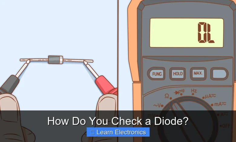
What if my multimeter shows “OL” or a very low reading in both directions?
If you get “OL” in both directions when you check a diode, it’s open and effectively dead. If it shows a very low resistance or “0” in both directions, it’s shorted, meaning it’s failed and won’t block current – time for a replacement!
📑 Table of Contents
Understanding the Diode: A Brief Overview
Before delving into the methods of testing, it’s crucial to understand what a diode is and how it functions. A diode is a two-terminal semiconductor device that essentially acts as a one-way valve for electric current. It allows current to flow easily in one direction (known as the forward direction) and largely blocks current flow in the opposite direction (the reverse direction).
Basic Function and Types
The two terminals of a diode are called the anode (positive) and the cathode (negative). When a positive voltage is applied to the anode and a negative voltage to the cathode, the diode is forward-biased and conducts. If the polarities are reversed, it’s reverse-biased, and ideally, no current flows (except for a very small leakage current). Common types include rectifier diodes, Zener diodes, light-emitting diodes (LEDs), and Schottky diodes, each with specific characteristics and applications.
Why Is Diode Verification Important?
Checking diodes is not just a routine step; it’s a critical aspect of electronics work that impacts troubleshooting, design, and repair. A faulty diode can lead to a range of circuit problems, from complete non-functionality to intermittent issues that are difficult to diagnose.
Troubleshooting Circuits
When a circuit fails or behaves unexpectedly, diodes are often among the first components to be suspected. They are susceptible to damage from overcurrent, overvoltage, and heat. Properly checking these components can quickly pinpoint a problem, saving significant time and effort in the troubleshooting process.
Ensuring Component Integrity
Even new components can sometimes be faulty from manufacturing defects, or components retrieved from old circuits might have degraded. Verifying their functionality before installation ensures that you are working with reliable parts, which is essential for the longevity and performance of any electronic device.
Essential Tools for Diode Testing
To accurately check a diode, you’ll need the right equipment. The primary tool is a multimeter, which can be either digital or analog.
Digital Multimeter (DMM)
A digital multimeter is the most common and recommended tool for diode testing. Most modern DMMs come with a dedicated “diode test” function, which is specifically designed for this purpose. This mode typically measures the forward voltage drop across the diode when a small current is passed through it.
Analog Multimeter (AMM)
While less precise than a DMM, an analog multimeter can also be used, primarily in its resistance (Ohms) range. Analog meters work by sending a small current from their internal battery through the component. The advantage here is that the positive lead of an analog meter is internally connected to the negative terminal of its battery in resistance mode, which can sometimes simplify the testing process for certain diodes.
Other Tools (Optional)
- Power Supply and Resistor: For a very basic, functional check without a multimeter, you can use a low-voltage DC power supply (e.g., 9V battery) and a current-limiting resistor (e.g., 1kΩ). This method primarily confirms if the diode conducts in one direction and blocks in the other, but doesn’t give precise voltage drop readings.
- Component Tester: Some advanced component testers can automatically identify and test various components, including diodes, providing detailed parameters.
How Do You Check a Diode? – Methods and Procedures
The most common and effective way to test a diode involves using a multimeter. Here’s a detailed breakdown of the primary methods.
Using a Digital Multimeter in Diode Test Mode
This is the preferred method for its accuracy and ease of use. The diode test function on a DMM applies a small voltage across the diode and displays the forward voltage drop.
- Set your DMM: Turn the rotary switch to the diode symbol (often represented by an arrow pointing to a line, like ➡️|).
- Identify Diode Terminals: Locate the anode and cathode on the diode. The cathode is usually marked with a band or stripe.
- Forward Bias Test:
- Connect the red (positive) probe to the anode.
- Connect the black (negative) probe to the cathode.
- A good silicon diode will display a voltage reading typically between 0.5V and 0.8V (around 0.2V-0.3V for germanium or Schottky diodes). This is its forward voltage drop.
- If it reads 0V or a very low value, the diode is likely shorted.
- If it reads OL (Open Loop) or ‘1’ (indicating infinite resistance), the diode is likely open.
- Reverse Bias Test:
- Reverse the probes: Connect the red (positive) probe to the cathode.
- Connect the black (negative) probe to the anode.
- A good diode should display OL or ‘1’ (indicating infinite resistance). This shows it’s blocking current in the reverse direction.
- If it displays any voltage reading (especially similar to the forward voltage drop), the diode is likely shorted.
- If it still displays a forward voltage drop, it is shorted.
Using a Digital Multimeter in Resistance Mode
If your DMM lacks a dedicated diode test mode, you can use the resistance (Ohms) setting, though it’s less precise.
- Set your DMM: Choose a mid-range resistance setting (e.g., 1kΩ or 10kΩ).
- Forward Resistance Test:
- Connect the red probe to the anode.
- Connect the black probe to the cathode.
- A good diode will show a low resistance reading (a few hundred Ohms to a few kOhms), indicating current flow.
- Reverse Resistance Test:
- Reverse the probes: Connect the red probe to the cathode.
- Connect the black probe to the anode.
- A good diode should show a very high resistance reading (usually ‘OL’ or ‘1’ on most DMMs, indicating an open circuit), as it blocks current.
If both tests show very low resistance, the diode is shorted. If both show infinite resistance, it’s open.
Using an Analog Multimeter
Analog multimeters can also perform diode tests using their resistance range. Remember that on most analog meters, the internal battery’s positive terminal is connected to the black probe, and the negative terminal to the red probe in resistance mode.
- Set your AMM: Select a resistance range (e.g., R x 100 or R x 1k).
- Forward Bias Test (Anode to Red, Cathode to Black):
- Connect the red probe to the anode.
- Connect the black probe to the cathode.
- The needle should deflect significantly to the right, indicating low resistance.
- Reverse Bias Test (Anode to Black, Cathode to Red):
- Reverse the probes: Connect the black probe to the anode.
- Connect the red probe to the cathode.
- The needle should remain far to the left, indicating very high resistance.
The Battery and Resistor Method (Basic Functional Check)
This method is for a quick check to see if the diode conducts, without precise measurements.
- Assemble the Circuit: Connect a 9V battery in series with a 1kΩ resistor and the diode. Use a small LED as an indicator if available.
- Forward Bias: Connect the positive terminal of the battery to the resistor, then to the diode’s anode, and the diode’s cathode to the negative terminal of the battery. If an LED is used, place it in series. The LED should light up (or you can measure a voltage drop across the resistor).
- Reverse Bias: Reverse the diode’s orientation. The LED should not light up (or no voltage drop across the resistor).
If it conducts in both directions or neither, the diode is faulty.
Interpreting Results and Common Diode Failures
Understanding what your multimeter readings mean is key to correctly identifying a faulty diode.
Good Diode Readings
- Forward Bias (Diode Test Mode): Displays a voltage drop (e.g., 0.5V to 0.8V for silicon).
- Reverse Bias (Diode Test Mode): Displays OL or ‘1’ (open circuit).
- Forward Bias (Resistance Mode): Low resistance reading.
- Reverse Bias (Resistance Mode): Very high or infinite resistance (OL).
Common Diode Failures
- Open Diode: The diode acts like a broken wire. It will show OL or infinite resistance in both forward and reverse bias. No current can flow through it in either direction.
- Shorted Diode: The diode acts like a regular wire or a very low resistance path. It will show 0V or a very low resistance reading in both forward and reverse bias. Current can flow freely in both directions, nullifying its rectifying function.
- Leaky Diode: This is a more subtle failure where the diode conducts a small amount of current in the reverse direction. On a multimeter, this might manifest as a very high but not infinite resistance in reverse bias, or a fluctuating reading. This type of fault is harder to detect with basic multimeter checks.
Diode Test Results Summary Table
This table summarizes what to expect when checking a diode with a digital multimeter in diode test mode:
| Diode Condition | Forward Bias (Red to Anode, Black to Cathode) | Reverse Bias (Red to Cathode, Black to Anode) |
|---|---|---|
| Good Diode (Silicon) | 0.5V – 0.8V (forward voltage drop) | OL (Open Loop) or ‘1’ |
| Open Diode | OL or ‘1’ | OL or ‘1’ |
| Shorted Diode | ~0.00V (or very low reading) | ~0.00V (or very low reading) |
| Leaky Diode | 0.5V – 0.8V | High but finite resistance (not OL) |
Safety Precautions and Best Practices for Diode Verification
When performing any electrical test, safety should always be your top priority. Following best practices ensures accurate readings and protects both you and your equipment.
Power Off Circuits
Always ensure the circuit under test is completely powered off and discharged before testing components like diodes. Testing components in-circuit can lead to false readings due to parallel components or damage your multimeter.
Proper Probe Handling
Hold multimeter probes by their insulated handles to avoid accidental shocks or short circuits. Ensure good contact with the component leads for accurate readings.
Consult Datasheets
For critical applications or unfamiliar diodes, always refer to the component’s datasheet. This will provide the exact forward voltage drop, reverse breakdown voltage, and other important parameters, helping you interpret your test results more accurately.
Test Out of Circuit Where Possible
For the most reliable results, it’s always best to desolder at least one lead of the diode from the circuit board before testing. This isolates the component and prevents other components in the circuit from affecting your readings.
Conclusion
Knowing how do you check a diode is an indispensable skill in electronics. Whether you’re troubleshooting a malfunctioning device, building a new circuit, or simply curious about component functionality, the ability to accurately verify a diode’s health is crucial. By utilizing a digital multimeter in its diode test mode, or even its resistance mode, you can quickly and effectively identify good, open, or shorted diodes. Always remember to prioritize safety, power down circuits, and follow best practices to ensure reliable results in all your electronic endeavors. Mastering this simple yet fundamental technique will significantly enhance your electronics diagnostic capabilities.
Frequently Asked Questions
How do I perform a basic test on a diode?
To perform a basic test, set your multimeter to the diode test mode. Connect the red (positive) probe to the diode’s anode and the black (negative) probe to its cathode. Note the reading, then reverse the probes and note that reading.
What multimeter settings do I use to check a diode?
You should use the diode test function on your digital multimeter, often indicated by a diode symbol. If your multimeter doesn’t have this specific mode, you can use the resistance (ohms) setting, typically on a low range like 1kΩ, but the diode test mode is more accurate.
What should a good diode read in forward bias?
In forward bias (red probe on anode, black on cathode), a good silicon diode will typically show a voltage drop between 0.5V and 0.8V. Germanium diodes will show a lower drop, usually around 0.2V to 0.3V. This reading indicates the voltage required to turn the diode on.
What should a good diode read in reverse bias?
In reverse bias (red probe on cathode, black on anode), a good diode should show an open circuit or “OL” (Over Load) on your multimeter display. This indicates very high resistance, meaning no current is flowing through the diode in this direction. Any significant voltage reading suggests a leaky or shorted diode.
How do I know if a diode is bad or failed?
A diode is likely bad if it shows an open circuit (OL) in both forward and reverse bias, indicating it’s completely broken. It’s also bad if it shows a very low resistance or a short circuit in both directions, meaning it’s failed short. If it shows current leakage in reverse bias, it’s also considered faulty.
How do I identify the anode and cathode when checking a diode?
Most diodes have a band or stripe on one end, which marks the cathode (negative terminal). The opposite end without the band is the anode (positive terminal). This marking helps you correctly orient the diode for testing and installation in a circuit.
As an Amazon Associate, I earn commission from qualifying purchases.


