How to Test Resistance with Multimeter? This essential skill in electronics involves using a multimeter’s ohmmeter function to measure the opposition to current flow in a component or circuit. Mastering this technique allows for effective troubleshooting, component verification, and circuit analysis, empowering you to diagnose and repair electronic devices with confidence.
The practice of measuring resistance is fundamental for anyone working with electronics, from hobbyists to professional technicians. It provides critical insights into the health and functionality of various components, making it an indispensable diagnostic tool in a wide range of applications.
Quick Answers to Common Questions
Why do I need to test resistance with a multimeter?
Testing resistance with a multimeter is essential for troubleshooting circuits, checking the health of components like resistors or wires, and identifying shorts or open circuits. It’s a key step to diagnose electrical problems and ensure everything is functioning correctly!
How do I set up my multimeter to test resistance?
First, always ensure the circuit or component you’re testing is completely de-energized for safety. Then, turn your multimeter’s dial to the Ohm (Ω) symbol and select the appropriate range if your multimeter isn’t auto-ranging, to accurately test resistance.
What does a good or bad resistance reading tell me?
A “good” resistance reading will typically match the expected value of the component or show continuity where anticipated. An extremely high or infinite reading usually indicates an open circuit, while a very low reading could signal a short, helping you pinpoint issues when you test resistance with your multimeter.
📑 Table of Contents
Understanding Resistance and Why It Matters
Before diving into the practical steps, it’s crucial to understand what electrical resistance is and why its measurement is so significant in the world of electronics. Resistance is one of the fundamental properties of a circuit, alongside voltage and current, as described by Ohm’s Law.
What is Electrical Resistance?
Electrical resistance is the opposition a material offers to the flow of electric current. It is measured in Ohms (Ω), named after German physicist Georg Ohm. Materials with high resistance, like rubber or plastic, are insulators, while materials with low resistance, like copper or silver, are conductors. Every electronic component, from a simple resistor to a complex integrated circuit, exhibits some level of resistance.
Why Measure Resistance?
Measuring resistance with a multimeter serves several critical purposes in electronics:
- Troubleshooting Circuits: Abnormal resistance readings can indicate faults like open circuits (infinite resistance), short circuits (near-zero resistance), or component failure.
- Component Verification: You can verify if a resistor has its stated value, check the continuity of wires, or test the functionality of switches and potentiometers.
- Circuit Design and Repair: Understanding component resistance is vital for designing circuits that function correctly and for replacing faulty parts with appropriate equivalents during repair.
- Safety Checks: Ensuring proper grounding or insulation resistance can be crucial for electrical safety.
Essential Tools: Your Multimeter and Probes
The primary tool for this task is a multimeter, a versatile device capable of measuring voltage, current, and resistance. Understanding its basic features is key to accurate measurements.
Anatomy of a Multimeter
A typical digital multimeter (DMM) features:
- Display: Shows the measurement reading.
- Rotary Dial: Used to select the measurement function (e.g., V for voltage, A for current, Ω for resistance) and the range (if not auto-ranging).
- Input Jacks: Typically include a COM (common) jack for the black probe, a VΩmA jack for voltage, resistance, and milliamps, and sometimes a separate 10A jack for higher current measurements.
- Probes: Consist of a black (negative) and a red (positive) test lead.
For measuring resistance, you’ll specifically look for the Ohm (Ω) symbol on the rotary dial.
Types of Multimeters
- Digital Multimeters (DMMs): Most common today, offering precise digital readouts, auto-ranging capabilities, and often more features.
- Analog Multimeters: Feature a needle and a scale. While still used, they can be harder to read precisely for resistance due to non-linear scales.
Safety First
Crucial Rule: NEVER measure resistance on a live circuit. Doing so can damage your multimeter, create a short circuit, or cause an electrical shock. Always ensure the circuit or component is completely powered down and de-energized before connecting your multimeter. For capacitors, ensure they are discharged before measuring.
Step-by-Step Guide to Testing Resistance with Multimeter
This section outlines the precise steps for obtaining accurate resistance measurements. Following these instructions carefully will ensure both your safety and the validity of your readings.
Preparation: Power Down and Isolate
- De-energize the Circuit: Turn off the power supply to the circuit or component you intend to test. Unplug devices from wall outlets.
- Discharge Capacitors: If the circuit contains large capacitors, discharge them safely using a resistor or by shorting their terminals (only after power is off and you’re certain it’s safe).
- Isolate the Component: For the most accurate reading, it’s best to remove the component from the circuit entirely. If you can’t, at least disconnect one lead of the component. Measuring in-circuit can lead to inaccurate readings due to parallel paths in the circuit.
Setting Up Your Multimeter
- Insert Probes: Plug the black test lead into the “COM” (common) jack. Plug the red test lead into the jack labeled “VΩmA” or similar (the one designated for voltage, resistance, and sometimes current).
- Select Ohms Function: Turn the rotary dial to the Ohm (Ω) symbol.
- Select Range (if manual): If your multimeter is not auto-ranging, you’ll need to select an appropriate range. Start with a higher range and work your way down. For example, if you expect a 1kΩ resistor, start with the 2kΩ or 20kΩ range. If the reading is “OL” (overload) or “1.” on the left, the resistance is higher than the selected range; switch to a higher range. If you get a very small number like “0.00,” the resistance is lower than the selected range; switch to a lower range for more precision.
- Calibrate (Analog Meters): For analog multimeters, short the two probes together and adjust the “Ohms Adjust” knob to make the needle point exactly to zero.
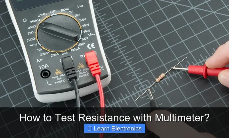
Taking the Measurement
- Touch the Probes: With the multimeter set up, touch the tip of one probe to one lead of the component and the tip of the other probe to the other lead. The polarity of the probes does not matter for resistance measurement; the reading will be the same regardless of which probe touches which lead.
- Observe the Reading: The multimeter display will show the resistance value in Ohms (Ω), Kilo-Ohms (kΩ), or Mega-Ohms (MΩ).
Interpreting the Readings
- Expected Value: Compare the measured resistance to the expected value (e.g., from a resistor’s color code, a component’s datasheet, or a circuit diagram). A reading within a small tolerance (e.g., ±5% or ±10%) is usually acceptable.
- “OL” or “1.” (Overload): This indicates an open circuit or a resistance higher than the multimeter’s maximum range. For continuity tests, this means there’s a break in the circuit.
- Near Zero Ohms: A reading very close to 0 Ω suggests a short circuit or a continuous path with very low resistance. For continuity tests, this confirms a good connection.
- Fluctuating Readings: Unstable readings can indicate a loose connection, an intermittent fault, or a faulty component like a potentiometer or thermistor that changes resistance with environmental factors.
Practical Applications and Troubleshooting Tips
Now that you know how to test resistance with multimeter, let’s explore some common scenarios where this skill is invaluable.
Testing Resistors
Resistors are fundamental components. To test one:
- Identify its nominal value using its color bands or markings.
- Measure its resistance as described above.
- Compare the measured value to the nominal value. A slight deviation (within its tolerance) is normal. Significant deviation suggests the resistor is faulty.
Checking Wires and Cables (Continuity)
Continuity is simply a complete path for current to flow. To test for continuity:
- Set your multimeter to the lowest Ohm range or to the dedicated continuity setting (often marked with a sound wave icon, which beeps when continuity is detected).
- Touch the probes to each end of the wire or cable segment.
- A reading near 0 Ω or a beep indicates continuity (a good connection). “OL” or no beep indicates an open circuit (a broken wire).
Diagnosing Circuit Problems
- Open Circuits: If a path where there should be current flow shows “OL,” you have an open circuit. This could be a broken wire, a blown fuse, or a failed component.
- Short Circuits: If a path that should have significant resistance (or no connection) shows near 0 Ω, you have a short circuit. This often leads to excessive current flow and can damage components or power supplies.
- Component Failure: By checking the resistance of individual components against their expected values, you can pinpoint faulty parts.
Testing Other Components
While specific testing methods vary, resistance measurement is useful for:
- Switches: Measure resistance across the terminals. It should be near 0 Ω when ON and “OL” when OFF (or vice versa, depending on the switch type).
- Potentiometers: Measure resistance across the two outer terminals (should be fixed). Then measure from a wiper to an outer terminal; this value should change as the knob is turned, and the sum of the two wiper-to-outer-terminal resistances should equal the fixed end-to-end resistance.
- Thermistors: These are temperature-dependent resistors. Their resistance will change significantly with temperature. You can test them by measuring their resistance at room temperature and comparing it to the datasheet value, or by observing how the resistance changes when heated or cooled.
Common Pitfalls and Advanced Considerations
Even with careful execution, certain factors can influence your resistance readings. Being aware of these can help you achieve more accurate and reliable results.
Inaccurate Readings
- Contact Resistance: Poor contact between the multimeter probes and the component leads can introduce additional resistance, leading to artificially high readings. Ensure a firm, clean connection.
- Multimeter Battery: A weak battery in your multimeter can affect its accuracy, especially for resistance measurements, as the meter itself provides a small current for the test.
- Component Temperature: The resistance of most materials changes with temperature. For precise measurements, ensure components are at a stable, known temperature.
- Skin Resistance: Holding both probes or touching both ends of a small component with your bare hands can add your body’s resistance (which can be thousands of Ohms) to the reading, especially for high-value resistors. Hold components by their insulation or leads, or place them on a non-conductive surface.
Auto-Ranging vs. Manual Ranging
- Auto-Ranging: Most modern DMMs automatically select the appropriate range for the measurement. This is convenient but can sometimes be slower for rapidly changing values.
- Manual Ranging: Requires the user to select the range. This can be faster once you know the approximate resistance, but selecting an incorrect range can lead to “OL” or less precise readings.
Measuring Very Low or Very High Resistance
- Very Low Resistance (milliohms): Standard multimeters struggle with very low resistance due to their internal resistance and lead resistance. Specialized meters like Kelvin bridges or 4-wire resistance meters are used for precision measurements in this range.
- Very High Resistance (gigaohms): Standard multimeters might show “OL” for extremely high resistances, common in insulation testing. Megohmmeters (insulation testers) apply higher voltages to accurately measure these vast resistances.
Resistance Measurement Reference Table
This table provides approximate resistance values for common scenarios and components. These are typical values and can vary based on specific components or conditions.
| Scenario/Component | Typical Resistance Range | Interpretation |
|---|---|---|
| Good Wire/Cable Continuity | 0.1 Ω – 2 Ω | Indicates a healthy, continuous path. |
| Open Circuit (Broken Wire, Blown Fuse) | OL (Overload) / Infinite | No electrical path, circuit is broken. |
| Short Circuit | 0 Ω (or very close to 0 Ω) | Unintended direct path for current, often a fault. |
| Healthy Standard Resistor (e.g., 1kΩ) | 950 Ω – 1050 Ω (for 5% tolerance) | Within expected tolerance of its marked value. |
| Closed Switch/Button | 0 Ω – 5 Ω | Current can flow through. |
| Open Switch/Button | OL (Overload) / Infinite | Current cannot flow through. |
| Human Skin Resistance (dry, hand to hand) | 100,000 Ω – 1,000,000 Ω (100 kΩ – 1 MΩ) | Highly variable, but significant. Why you shouldn’t touch probes with bare hands. |
| Insulation (e.g., good wire insulation) | >1 MΩ (often hundreds of MΩ or GΩ) | High resistance preventing current leakage. |
Always refer to component datasheets or manufacturer specifications for precise expected resistance values.
Conclusion
Testing resistance with a multimeter is an invaluable skill for anyone involved with electronics. It’s a fundamental diagnostic technique that allows you to quickly assess the health of components and identify problems within circuits. By understanding what resistance is, how to properly set up and use your multimeter, and how to interpret the readings, you gain a powerful capability for troubleshooting and repair.
Remember to always prioritize safety by de-energizing circuits before making measurements and being mindful of potential pitfalls that can lead to inaccurate readings. With practice, using a multimeter for resistance measurements will become second nature, greatly enhancing your ability to work confidently and effectively with electronic systems.
Frequently Asked Questions
What is electrical resistance, and why do I need to test it with a multimeter?
Electrical resistance is a measure of how much a material opposes the flow of electric current. Testing resistance with a multimeter helps identify faulty components, check circuit continuity, and ensure proper functionality of electrical devices. It’s a fundamental step in diagnostics and troubleshooting.
How do I set my multimeter to measure resistance (Ohms)?
To measure resistance, you need to set your multimeter to the Ohms (Ω) function. On most digital multimeters, this is typically indicated by the Greek letter Omega symbol. If your multimeter is manual ranging, select an appropriate range higher than the expected resistance; auto-ranging multimeters will automatically adjust.
What are the correct steps to connect the probes for testing resistance with a multimeter?
First, ensure the circuit or component you’re testing is completely de-energized and disconnected from any power source for safety. Insert the red test lead into the VΩmA jack and the black test lead into the COM jack. Then, touch the probes across the two points of the component or circuit where you want to measure resistance.
What does “OL” or “1” mean when my multimeter displays it while testing resistance?
When your multimeter displays “OL” (Over Limit) or “1” on the far left, it usually indicates an open circuit or a resistance value higher than the selected range. This means there is no complete path for current, or the resistance is too high for the current setting. You might need to select a higher Ohm range or confirm the circuit isn’t broken.
Can I safely test resistance on a circuit that is powered on?
No, you must never test resistance on a live or powered circuit. Doing so can provide inaccurate readings, damage your multimeter, or even create a safety hazard. Always ensure the component or circuit is completely de-energized and isolated from any power source before attempting to measure resistance.
How do I interpret the resistance reading displayed on my multimeter?
The resistance reading will be displayed in Ohms (Ω), kilohms (kΩ), or megohms (MΩ). A lower number indicates less opposition to current flow, meaning good continuity or a conductive path. A higher number or “OL” suggests higher opposition, an open circuit, or a faulty component.
As an Amazon Associate, I earn commission from qualifying purchases.


