Learning how to use a multimeter is essential for anyone working with electronics or electrical systems, providing crucial insights into circuit behavior and component health. This versatile instrument is fundamental for troubleshooting, testing, and verifying electrical parameters safely and efficiently. Mastering this technique empowers you to diagnose issues and ensure the proper functioning of various devices.
The practice of using this device spans from simple battery checks to complex circuit analysis, making it an indispensable tool for hobbyists, technicians, and professionals alike. Understanding its capabilities and proper operation is the first step towards confidently interacting with the world of electricity.
Quick Answers to Common Questions
What exactly does a multimeter measure?
A multimeter is a fantastic tool that measures various electrical properties like voltage (volts), current (amperes), and resistance (ohms), making it essential for troubleshooting electronics and wiring.
How do I measure voltage safely with my multimeter?
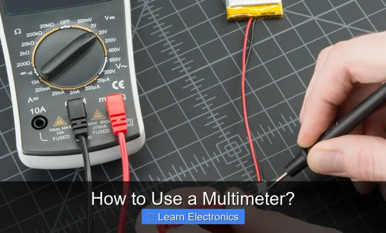
To measure voltage, plug the red lead into the VΩmA port and the black lead into COM. Then, set your multimeter to the appropriate ACV or DCV range and carefully touch the probes to the two points you want to measure.
What’s continuity, and why would I check it with a multimeter?
Continuity checks if an electrical path is complete or broken. You’d use your multimeter’s continuity setting (it often beeps!) to test cables, fuses, or circuit traces to ensure current can flow freely through them.
📑 Table of Contents
- Understanding Your Multimeter: The Essential Tool
- Safety First: Essential Precautions for Using a Multimeter
- Basic Measurements: Voltage (Volts)
- Basic Measurements: Resistance (Ohms) and Continuity
- Basic Measurements: Current (Amps)
- Advanced Functions and Best Practices for How to Use a Multimeter
- Conclusion
Understanding Your Multimeter: The Essential Tool
Before diving into specific measurements, it’s crucial to familiarize yourself with the multimeter itself. This device is an electronic measuring instrument that combines several measurement functions in one unit. Modern digital multimeters (DMMs) are the most common, offering clear displays and often auto-ranging capabilities, simplifying the measurement process.
Types of Multimeters: Analog vs. Digital
- Analog Multimeters: These older models feature a needle that moves across a scale to indicate readings. They are generally less precise and can be harder to read accurately due to parallax error. However, some prefer them for observing rapidly changing values, as the needle’s movement can be more intuitive than a rapidly updating digital display.
- Digital Multimeters (DMMs): DMMs display readings as numerical values on an LCD screen, offering higher precision and ease of reading. Many come with advanced features like auto-ranging (automatically selecting the correct measurement range), backlighting, and data hold functions. They are the go-to choice for most users today due to their accuracy and user-friendliness.
Key Components and Controls
Regardless of whether you have an analog or digital model, most multimeters share common components:
- Display: Shows the measured values (digital) or has a scale with a needle (analog).
- Function Dial/Rotary Switch: This is the central control that allows you to select what you want to measure (e.g., voltage, current, resistance) and the measurement range (if not auto-ranging).
- Input Jacks/Ports: These are where you plug in the test leads. Typically, there are three or four jacks:
- COM (Common): This is for the black (negative) test lead and always remains connected.
- VΩmA (or similar): For measuring voltage, resistance, and sometimes low current.
- 10A (or similar high current): For measuring high current (usually up to 10 Amps). Always use the correct jack for the measurement.
- Test Leads/Probes: These are insulated wires with a sharp metal tip for making contact with the circuit. They typically come in red (positive) and black (negative).
Safety First: Essential Precautions for Using a Multimeter
Electrical measurements can be dangerous if not performed correctly. Adhering to safety precautions is paramount when working with this device to prevent injury or damage to equipment.
Personal Protective Equipment (PPE)
- Safety Glasses: Always wear safety glasses to protect your eyes from arcs or flying debris.
- Insulated Gloves: For higher voltage work, insulated gloves provide an extra layer of protection against electric shock.
- Appropriate Clothing: Avoid loose clothing or jewelry that could snag on components or conduct electricity.
De-energizing Circuits
Whenever possible, disconnect power to the circuit you are testing, especially when measuring resistance or continuity, or working on components that could short-circuit. If measuring live voltage or current, exercise extreme caution.
Proper Probe Handling
- One Hand Rule: Whenever feasible, try to make measurements with only one hand. This minimizes the chance of current flowing through your chest and heart if you accidentally touch a live wire.
- Inspect Leads: Before each use, check your test leads for any nicks, cuts, or cracked insulation. Damaged leads are a significant safety hazard.
- Connect Common First: Always connect the black (COM) lead to the common or ground point of the circuit first, then connect the red (positive) lead. When finished, disconnect the red lead first.
Basic Measurements: Voltage (Volts)
Voltage is the electrical potential difference between two points in a circuit, measured in volts (V). It’s essentially the “push” or “pressure” that drives current. A multimeter measures voltage in parallel with the component or circuit you are testing.
Measuring AC Voltage (Alternating Current)
AC voltage is typically found in wall outlets and is characterized by its sinusoidal waveform. To measure AC voltage:
- Plug the black test lead into the COM jack.
- Plug the red test lead into the VΩmA jack.
- Turn the function dial to the AC voltage setting (often represented by a V with a wavy line or “VAC”).
- If your multimeter is not auto-ranging, select a range higher than the expected voltage (e.g., 200V for a 120V outlet).
- Carefully touch the red probe to one point of the AC source and the black probe to the other. For a wall outlet, insert probes into the slots (one into the hot, one into the neutral, or hot and ground for checking ground integrity).
- Read the voltage displayed on the screen.
Measuring DC Voltage (Direct Current)
DC voltage is common in batteries, automotive systems, and electronic circuits. It flows in one direction. To measure DC voltage:
- Plug the black test lead into the COM jack.
- Plug the red test lead into the VΩmA jack.
- Turn the function dial to the DC voltage setting (often represented by a V with a straight line, or “VDC”).
- If not auto-ranging, select a range higher than the expected voltage (e.g., 20V for a 9V battery).
- Touch the red probe to the positive (+) terminal of the DC source and the black probe to the negative (-) terminal.
- Read the voltage. A positive reading indicates correct polarity; a negative reading means the probes are reversed, though the voltage magnitude is still correct.
Basic Measurements: Resistance (Ohms) and Continuity
Resistance is the opposition to the flow of electric current, measured in ohms (Ω). Continuity is a simple test to determine if there’s an unbroken path for current to flow.
Measuring Resistance
Resistance measurements are typically performed on de-energized circuits. Never measure resistance on a live circuit, as it can damage the multimeter.
- Ensure the circuit or component is not powered.
- Plug the black test lead into the COM jack.
- Plug the red test lead into the VΩmA jack.
- Turn the function dial to the resistance setting (Ω).
- If not auto-ranging, select an appropriate range.
- Touch the probes across the component you want to measure. For a resistor, touch one probe to each end.
- Read the resistance value. An “OL” or “1” reading usually indicates an open circuit or resistance higher than the selected range.
Checking Continuity
Continuity is a quick way to check if a wire is broken or if a switch is working. Many multimeters have a dedicated continuity setting that emits a beep if there’s a continuous path (low resistance).
- Ensure the circuit or component is not powered.
- Plug the black test lead into the COM jack.
- Plug the red test lead into the VΩmA jack.
- Turn the function dial to the continuity setting (often indicated by a speaker symbol or an arrow with a dot).
- Touch the probes to both ends of the wire or across the switch terminals.
- If the multimeter beeps and shows a very low resistance (close to 0Ω), there is continuity. No beep or an “OL” reading indicates an open circuit.
Basic Measurements: Current (Amps)
Current is the rate of flow of electric charge, measured in amperes (A). Measuring current is different from voltage and resistance because it requires inserting the multimeter in series with the circuit, meaning you must break the circuit to take a reading.
Warning: Never connect the multimeter in parallel with a voltage source when measuring current, as this will create a short circuit and likely blow the multimeter’s fuse or damage the device. Always start with the highest current range to avoid overloading the meter.
Measuring AC Current
Measuring AC current usually requires a clamp meter (a type of multimeter that measures current non-invasively by clamping around a wire), but some standard DMMs have AC current ranges.
- De-energize the circuit.
- Plug the black test lead into the COM jack.
- Plug the red test lead into the 10A (or appropriate mA/μA) jack, depending on the expected current.
- Turn the function dial to the AC current setting (A with a wavy line, or “ACA”).
- Open the circuit at the point where you want to measure current.
- Connect the multimeter in series with the circuit. The current flows through the multimeter.
- Apply power to the circuit.
- Read the current displayed.
Measuring DC Current
DC current measurements follow a similar procedure:
- De-energize the circuit.
- Plug the black test lead into the COM jack.
- Plug the red test lead into the 10A (or appropriate mA/μA) jack.
- Turn the function dial to the DC current setting (A with a straight line, or “DCA”).
- Open the circuit at the desired measurement point.
- Connect the multimeter in series. Ensure correct polarity (red to the point closer to the positive supply, black to the point closer to the negative supply).
- Apply power to the circuit.
- Read the current.
Advanced Functions and Best Practices for How to Use a Multimeter
Beyond the basic measurements, many digital multimeters offer a range of additional functions that enhance their utility for more complex troubleshooting and analysis. Understanding these advanced features can significantly broaden your diagnostic capabilities.
Diode Test
Diodes are semiconductor devices that allow current to flow in one direction only. The diode test mode checks the integrity and forward voltage drop of a diode:
- Select the diode symbol setting on the dial.
- Place the red probe on the anode and the black probe on the cathode. A good diode will display a forward voltage drop (typically 0.5V to 0.7V for silicon diodes).
- Reverse the probes. A good diode should display “OL” (open circuit), indicating no current flow in the reverse direction.
Capacitance Measurement
Capacitors store electrical energy and are crucial components in many circuits. Some multimeters can measure capacitance in Farads (F).
- Ensure the capacitor is fully discharged before testing to prevent damage to the meter or injury.
- Select the capacitance setting (often denoted by a capacitor symbol).
- Connect the probes across the capacitor terminals.
- The multimeter will display the capacitance value.
Frequency Measurement
Frequency (Hz) is the number of cycles per second of an alternating waveform. Some multimeters can measure the frequency of AC signals.
- Select the frequency setting (Hz).
- Connect the probes across the point in the circuit where you want to measure the frequency.
- The display will show the frequency in Hertz.
Data Table: Common Multimeter Symbols and Their Functions
| Symbol | Function | Description |
|---|---|---|
 V~ V~ | AC Voltage | Measures alternating current voltage. |
 V– V– | DC Voltage | Measures direct current voltage. |
 Ω Ω | Resistance | Measures electrical resistance in ohms. |
 | Continuity | Checks for an unbroken electrical path, often with an audible beep. |
| A~ | AC Current | Measures alternating current in amperes. |
| A– | DC Current | Measures direct current in amperes. |
 | Diode Test | Tests the functionality of diodes. |
 | Capacitance | Measures capacitance in Farads. |
| Hz | Frequency | Measures the frequency of an AC signal in Hertz. |
Tips for Accurate Readings and Troubleshooting:
- Choose the Right Range: If your multimeter isn’t auto-ranging, always start with the highest range and work your way down. This prevents overloading the meter and ensures a more precise reading.
- Check Your Leads: Ensure your test leads are correctly plugged into the appropriate jacks for the desired measurement.
- Clean Contact Points: Dirty or corroded contact points can lead to inaccurate readings. Clean them with an abrasive or contact cleaner if necessary.
- Battery Check: If your meter uses batteries, ensure they are fresh, as low battery power can affect accuracy.
- Read the Manual: Every multimeter has unique features and specific instructions. Always consult your device’s user manual for detailed guidance.
Conclusion
A multimeter is an indispensable tool for anyone involved in electronics or electrical work. By understanding its basic functions—measuring voltage, current, and resistance—and adhering to proper safety protocols, you can confidently diagnose, troubleshoot, and verify electrical systems. This comprehensive approach to using the instrument not only ensures accurate readings but also prioritizes your safety and the longevity of your equipment. With practice, using this versatile device will become second nature, opening up a world of possibilities for your electronic projects and repairs.
Frequently Asked Questions
What is a multimeter and what can it measure?
A multimeter is a versatile electronic measuring instrument that combines several measurement functions into one unit. It is primarily used to measure voltage (volts), current (amps), and resistance (ohms) in electrical circuits, making it an indispensable tool for electricians, hobbyists, and technicians.
How do I select the right setting on my multimeter for a measurement?
To select the right setting, first identify what you want to measure (e.g., AC voltage, DC voltage, resistance, current). Then, turn the rotary dial on your multimeter to the corresponding function and range. Always start with a higher range if you’re unsure of the expected value to prevent damaging the meter.
What are the essential safety precautions when using a multimeter?
Always ensure the circuit you are testing is de-energized if you are measuring current or resistance, and never touch the metal tips of the probes while the circuit is live. Use appropriate personal protective equipment like safety glasses, and confirm your multimeter’s CAT rating matches the circuit’s voltage level.
How do I measure voltage using a multimeter?
To measure voltage, set your multimeter to the appropriate AC (~) or DC (V=) voltage range. Connect the red probe to the VΩmA jack and the black probe to the COM jack. Then, place the probes in parallel across the component or power source you want to measure, ensuring the circuit is live.
Can I test continuity with a multimeter, and what does it indicate?
Yes, most multimeters have a continuity function, often indicated by a speaker or diode symbol. This setting tests if there’s a complete electrical path between two points or if a wire is broken. If the multimeter beeps, it indicates a continuous circuit with very low resistance.
As an Amazon Associate, I earn commission from qualifying purchases.


