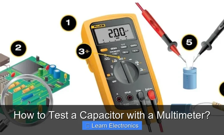
How to Test a Capacitor with a Multimeter? This essential skill is invaluable for anyone troubleshooting electronic circuits, allowing you to quickly identify faulty components. Understanding this method helps in diagnosing issues in power supplies, motor controls, and various other electronic devices effectively.
The process of checking capacitors with a multimeter is straightforward once you know the steps. This technique relies on measuring the capacitor’s charging and discharging characteristics, or its capacitance directly, depending on your multimeter’s capabilities.
Quick Answers to Common Questions
What’s the right multimeter setting to test a capacitor for its actual value?
For the most accurate results, use your multimeter’s dedicated capacitance (µF, nF, pF) setting. Remember to fully discharge the capacitor before connecting the leads to get a reading close to its marked value.
My multimeter doesn’t have a capacitance function. Can I still test a capacitor with a multimeter?
Absolutely! You can perform a basic health check using the resistance (ohms) setting. A healthy capacitor will show the resistance briefly rising before settling, indicating it’s charging up properly.
How can I tell if a capacitor is good or bad based on the reading when I test a capacitor with a multimeter?
A good capacitor will show a capacitance reading close to its labeled µF value if your multimeter has that function. If using the resistance method, a quick initial resistance surge followed by a steady drop and then a consistent open circuit (or very high resistance) usually means it’s healthy, while no change or a continuous low reading suggests it’s faulty.
📑 Table of Contents
Understanding Capacitors and Why They Fail
Before diving into the testing process, it’s crucial to grasp what a capacitor does and why it might fail. Capacitors are fundamental electronic components found in nearly all circuits, from simple hobby projects to complex industrial machinery.
What is a Capacitor?
A capacitor is a passive two-terminal electrical component used to store electrical energy in an electric field. It consists of two conductive plates separated by a dielectric (insulating) material. When a voltage is applied across the plates, an electric charge builds up, effectively storing energy. Capacitors are used for filtering, smoothing power supplies, timing, coupling, and decoupling signals in circuits.
Common Capacitor Failures
Capacitors, especially electrolytic types, are notorious for failing over time due to heat, voltage stress, or manufacturing defects. Common failure modes include:
- Short Circuit: The dielectric material breaks down, creating a direct path between the plates. This can cause severe damage to the circuit.
- Open Circuit: The internal connection to one of the plates breaks, preventing the capacitor from storing charge. The component effectively becomes a break in the circuit.
- Leakage: The dielectric’s insulating properties degrade, allowing a small current to pass through even when fully charged. This reduces the capacitor’s effectiveness and can cause unstable circuit operation.
- Degradation of Capacitance: The actual capacitance value decreases over time, often due to electrolyte drying out in electrolytic capacitors, leading to poor filtering or timing.
Essential Tools for Capacitor Testing
To accurately test a capacitor, you’ll need the right equipment and a few safety precautions. A multimeter is the primary tool, but understanding its features is key.
Types of Multimeters for Testing
- Digital Multimeter (DMM): Most modern DMMs offer a resistance (ohms) range, which is suitable for basic capacitor checks. Many also include a dedicated capacitance measurement function (marked with an ′F′ for Farads), providing a direct reading of the capacitor’s value.
- Analog Multimeter: Analog meters can also be used for resistance checks, observing the needle’s movement. They are generally less precise for capacitance measurement but can still show charging behavior.
Safety Gear and Other Essentials
- Safety Glasses: Always wear eye protection when working with electronics, especially when dealing with potentially charged components.
- Insulated Gloves: Useful for handling components, particularly when discharging larger capacitors.
- Capacitor Discharge Tool: For larger capacitors (over 100µF or high voltage), a dedicated discharge tool (e.g., a power resistor with insulated leads) is safer than shorting the terminals.
- Alligator Clip Leads: Can make connections easier and safer during testing.
Safety First: Discharging Capacitors
This is arguably the most critical step before attempting any capacitor testing. Large capacitors can store significant electrical charge even after power is removed, posing a severe shock hazard or causing damage to your multimeter if not properly discharged.
Why Discharge is Crucial
A charged capacitor, especially a high-voltage one, can deliver a painful or even dangerous electric shock. Furthermore, connecting a charged capacitor directly to your multimeter can damage the meter’s internal circuitry, particularly its resistance measurement function.
The Proper Discharge Procedure
Always discharge a capacitor before handling or testing it. Here’s how:
- De-energize the Circuit: First, ensure the circuit containing the capacitor is completely unplugged or powered down.
- Wait (Optional but Recommended): For smaller capacitors (under 10µF) in many circuits, waiting a few minutes might be enough for them to self-discharge through internal leakage or associated components. However, never rely solely on this for larger or high-voltage capacitors.
- Use a Resistor: The safest and most controlled way to discharge a capacitor is by connecting a suitable resistor across its terminals. For most general-purpose electronics, a 1kΩ to 10kΩ resistor with a power rating of 0.5W to 2W is often sufficient.
- Connect one lead of the resistor to one terminal of the capacitor.
- Connect the other lead of the resistor to the other terminal of the capacitor.
- Hold the resistor in place (using insulated pliers or alligator clips) for several seconds to a minute, depending on the capacitor’s size and voltage. For very large capacitors, you might need to hold it longer or use a higher power resistor.
- Verify Discharge with Multimeter: After discharging, set your multimeter to DC voltage measurement (e.g., 200V DC range) and measure the voltage across the capacitor terminals. The reading should be very close to 0V. If not, repeat the discharge process.
Using Your Multimeter for Capacitor Diagnostics
Now that safety is covered, let’s explore How to Test a Capacitor with a Multimeter? using the resistance function, which is available on almost all multimeters.
Setting Up Your Multimeter (Resistance/Ohms Mode)
This test method works by observing the capacitor’s charging behavior as the multimeter itself applies a small voltage (from its internal battery) and measures the resulting current (which it interprets as resistance).
- Select Resistance Range: Set your multimeter to the highest resistance range (e.g., 2MΩ or 20MΩ). For smaller capacitors, you might use a lower range later, but always start high.
- Connect Leads: Plug the red test lead into the VΩmA jack and the black test lead into the COM jack.
- Polarity: For electrolytic capacitors, observe polarity. Connect the red (positive) lead to the positive terminal of the capacitor and the black (negative) lead to the negative terminal. For non-polarized capacitors, polarity doesn’t matter for this test.
The Resistance Test (Charging Behavior)
Connect the multimeter leads to the discharged capacitor and observe the resistance reading:
- Initial Reading: When you first connect the leads, the multimeter will typically show a low resistance value (or a rapid decrease from infinite resistance). This indicates the capacitor is drawing current as it begins to charge from the multimeter’s internal battery.
- Charging Progress: As the capacitor charges, the resistance reading on the multimeter should gradually increase.
- Final Reading: A good capacitor will eventually show an extremely high resistance value, often approaching infinity or “OL” (Over Limit) on a digital multimeter. This signifies that the capacitor has fully charged and is no longer drawing significant current.
The speed at which the resistance climbs depends on the capacitor’s capacitance. Larger capacitors will take longer to charge and thus longer for the resistance reading to stabilize at infinity. Smaller capacitors will charge almost instantaneously.
Understanding the Readings
Here’s what different readings might indicate:
- Good Capacitor: Starts low, gradually increases, and settles at infinite resistance (OL).
- Short-Circuited Capacitor: Shows a very low resistance (close to 0Ω) and stays there. This means the capacitor is effectively a short circuit.
- Open-Circuited Capacitor: Immediately shows infinite resistance (OL) and stays there. This indicates the capacitor isn’t taking any charge.
- Leaky Capacitor: Shows a high but not infinite resistance. It might charge up, but the resistance doesn’t reach OL, indicating a constant, small current flow.
Advanced Capacitor Testing Techniques
While the resistance test is good for basic fault detection, more advanced multimeters offer dedicated functions for precise capacitance measurement.
Capacitance Measurement (If Multimeter Has This Feature)
Many digital multimeters have a dedicated capacitance function, usually marked with a symbol like ′F′ for Farads (or nF, µF, mF). This is the most direct way to measure a capacitor’s value.
- Set Multimeter: Switch your DMM to the capacitance (F) range. It might have auto-ranging, or you might need to select a suitable range based on the capacitor’s marked value.
- Connect Capacitor: Connect the discharged capacitor directly to the multimeter’s test leads, observing polarity for electrolytic capacitors.
- Read Value: The multimeter will display the capacitance value in Farads (or sub-multiples like microfarads, nanofarads). Compare this reading to the value printed on the capacitor. A reading within +/-10-20% of the nominal value is generally considered acceptable for most capacitors.
If the reading is significantly off, fluctuating wildly, or showing “OL” when it shouldn’t, the capacitor is likely faulty.
ESR (Equivalent Series Resistance) Testing
ESR is a critical parameter for electrolytic capacitors, particularly in power supply filtering. A capacitor with high ESR, even if its capacitance value is still good, can fail to filter effectively, leading to circuit instability. While some advanced multimeters can measure ESR, dedicated ESR meters are often preferred for accurate diagnosis of this specific failure mode. High ESR is a common indicator of a “bad cap” even if the capacitance value seems okay.
Troubleshooting and Interpreting Results: How to Test a Capacitor with a Multimeter?
Once you’ve performed the tests, understanding what your readings mean is crucial for effective troubleshooting. This section will guide you through interpreting the results of the measurements.
What a Good Capacitor Looks Like
- Resistance Test: Shows a gradual increase from low resistance to infinite (OL) as it charges, then holds the infinite reading.
- Capacitance Test: Reads a value close to its marked capacitance (within typical tolerance, e.g., ±10-20%).
Signs of a Bad Capacitor
- Resistance Test:
- Stuck at Low Resistance (near 0Ω): Indicates a short circuit.
- Stuck at Infinite Resistance (OL) from the start: Indicates an open circuit.
- Settles at a High but Not Infinite Resistance: Indicates a leaky capacitor.
- Capacitance Test:
- Reads 0 or very low value: Significantly below its marked value, indicating an open circuit or severe degradation.
- Reads “OL” or “ERR”: May indicate an open circuit or component outside the meter’s range.
- Reads a short value: If the meter displays a short circuit indication, it confirms the resistance test finding.
- Physical Inspection: Always visually inspect capacitors. Look for signs like bulging tops, leaking electrolyte (often a brownish goo), or discolored shrink wrap. These are clear indicators of failure, even if your multimeter provides ambiguous results.
Practical Tips for Replacement
- Match Values: When replacing a capacitor, always match the capacitance (Farads) and voltage rating (Volts) exactly.
- Consider Temperature: If available, match the temperature rating (e.g., 85°C, 105°C). Higher temperature ratings generally mean better longevity.
- Polarity: For electrolytic capacitors, ensure you install the new one with the correct polarity. Reversing polarity can cause the capacitor to explode.
- ESR: For power supply applications, consider replacing with “low ESR” capacitors if the original was a low ESR type.
Here’s a quick reference table for common multimeter settings and expected outcomes:
| Test Type | Multimeter Setting | Good Capacitor Indication | Bad Capacitor Indication |
|---|---|---|---|
| Discharge Verification | DC Voltage (e.g., 200V DC) | Reads ~0V | Reads significant voltage |
| Resistance (Charging) Test | Highest Ohms (e.g., 2MΩ, 20MΩ) | Starts low, increases to OL/Infinity | Stuck low (short), stuck high (open), or settles high but not OL (leaky) |
| Capacitance Measurement | Capacitance (F, nF, µF) | Reads close to marked value (within tolerance) | Reads 0, OL, significantly off, or fluctuates |
Mastering how to test a capacitor with a multimeter is an invaluable skill for any electronics enthusiast or professional. By following the safety procedures and understanding the different testing methods, you can confidently diagnose faulty capacitors and extend the life of your electronic devices. Always prioritize safety, especially when dealing with potentially charged components.
Frequently Asked Questions
What multimeter setting should I use to test a capacitor?
For a basic functional check of electrolytic capacitors, you’ll typically use the resistance (Ohms, Ω) setting on your multimeter. Some more advanced digital multimeters also feature a dedicated capacitance (Farad, F) setting for precise value measurements.
How do I test a capacitor for functionality using a multimeter?
First, ensure the capacitor is fully discharged before handling it. Then, set your multimeter to the resistance (Ohms) range. Connect the multimeter leads to the capacitor terminals and observe the reading; a good capacitor will show a brief low resistance, then gradually rise towards infinity (open circuit) as it charges from the multimeter’s battery.
What do the readings indicate when testing a capacitor with a multimeter?
A functional capacitor will briefly display a low resistance before climbing to an open circuit (infinite resistance) as it charges. If the multimeter immediately shows zero resistance, the capacitor is likely shorted. If it instantly displays infinite resistance without charging, the capacitor is probably open or dead.
Can I test all types of capacitors effectively with a standard multimeter?
A standard multimeter set to resistance can perform basic checks for shorts or opens on electrolytic and some ceramic capacitors. However, for an accurate capacitance value measurement, especially for smaller capacitors or non-electrolytic types, a multimeter with a dedicated capacitance (Farad) function is highly recommended.
What safety steps should I take before testing a capacitor with a multimeter?
Always discharge the capacitor completely before touching its terminals or testing it, particularly large electrolytic capacitors, as they can store dangerous amounts of electrical charge. Use an appropriate resistor to safely discharge it across its terminals. Ensure the power to the circuit is disconnected before you begin any testing.
Why might my multimeter give an incorrect or confusing reading when testing a capacitor?
An incorrect reading could be due to the capacitor not being fully discharged, which interferes with resistance measurements. Additionally, if the capacitor is tested while still in a circuit, other components can provide alternate paths for current, leading to misleading readings. Always ensure good contact between the multimeter leads and the capacitor terminals.
As an Amazon Associate, I earn commission from qualifying purchases.


